Increasing voltage on kt 18 mosfet controller

Snacks

1 W
Joined
Feb 2, 2022
Messages
54
I’ve read more than a few posts on the subject but I wanted to make sure that I was doing this correctly for my own controller-

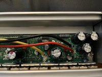
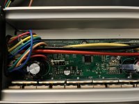
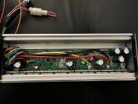
Ordered a 60v 45A 18 mosfet kt controller and received a 48V. They will give me a substantial refund if I keep this rather than exchange for the correct one. So I was wondering if I could swap out the cap and maybe the resistor to have this work correctly.

I checked the mosfets and they are rated at 85V 150A. They are K150E09NE

The caps are 63V so I know I have to change those to 100V but I wasn’t sure what else, if anything , I needed to change to get this controller to handle 60V

Also, the kt lcd8h that came with this controller was sold as a 48V but looking up the part , it seems they’re listed as 36/48/60V lcds on most sites . So I’m hoping I won’t have to replace this

Any help would be greatly appreciated!
 

Attachments

  • 6D9EBAB6-30B3-40F1-9580-2A0F49B1B518.jpeg
    6D9EBAB6-30B3-40F1-9580-2A0F49B1B518.jpeg
    3.5 MB · Views: 637
  • BB095BA4-E4FF-4127-B8E0-4C0C83B7F8B3.jpeg
    BB095BA4-E4FF-4127-B8E0-4C0C83B7F8B3.jpeg
    3.4 MB · Views: 635
  • A49F26E9-FC08-42C4-AD95-6A8F29DFD9C8.jpeg
    A49F26E9-FC08-42C4-AD95-6A8F29DFD9C8.jpeg
    3.5 MB · Views: 637
docw009 said:
As I recall, the reverse engineered schematics for the prototype KT controller showed an LM317T used to reduce the 48V down to 14V. I looked up the datasheet for that part, and it's running at its limit near 60V. Maybe KT is using a sturdier part.

ku63_schematic.jpg

S06S_schematic.pdf

thank you for that info! you are right, i just checked and they are still using the same part. although when i checked the datasheet it shows maximum input voltage as 40V so maybe im looking at the wrong data sheet but looks like ill have to find another part to replace that as well .
 
Snacks said:
maximum input voltage as 40V

Maximum differential input voltage of 40V. That's why a 48V nominal (54.6V max) battery doesn't instantly fry it. Or more accurately, the resistor in front of the LM317T is the reason why 54.6V doesn't instantly fry it.

Even when running at 48V the LM317T is critically hot without a heatsink. Outside maximum operating temperatures.

I've measured the controller + display + motor idling at 4W of power when on. There are switching DC-DC converters that can drop 60V to 15V but they are not incredibly efficient themselves, so swapping one in place of the LM317T would not be a large improvement.

I just stuck a heatsink on the LM317T to keep it within spec heat wise.

Technically you can just replace the large resistor with an even larger resistor to make the LM317T cope with higher voltages (and the input caps, obviously).
 
Comrade said:
Snacks said:
maximum input voltage as 40V

Maximum differential input voltage of 40V. That's why a 48V nominal (54.6V max) battery doesn't instantly fry it. Or more accurately, the resistor in front of the LM317T is the reason why 54.6V doesn't instantly fry it.

Even when running at 48V the LM317T is critically hot without a heatsink. Outside maximum operating temperatures.

I've measured the controller + display + motor idling at 4W of power when on. There are switching DC-DC converters that can drop 60V to 15V but they are not incredibly efficient themselves, so swapping one in place of the LM317T would not be a large improvement.

I just stuck a heatsink on the LM317T to keep it within spec heat wise.

Technically you can just replace the large resistor with an even larger resistor to make the LM317T cope with higher voltages (and the input caps, obviously).

ahh ok , that makes a lot of sense. thanks for explaining to me. ill probably just replace the resistor for a bigger one then.
looking up new 100v caps and a bigger resistor to purchase for these now.

if you or anyone here has any recommendations on some, that would be a great help
 
Snacks said:
looking up new 100v caps and a bigger resistor to purchase for these now.

What did you have in mind for the specs of the new resistor?
 
Comrade said:
Snacks said:
looking up new 100v caps and a bigger resistor to purchase for these now.

What did you have in mind for the specs of the new resistor?

To be honest , I’m not really sure. I was thinking I may have to measure the resistance on this one and then look for one but I didn’t have time to research how I should go about this yet.
 
Snacks said:
To be honest , I’m not really sure. I was thinking I may have to measure the resistance on this one and then look for one but I didn’t have time to research how I should go about this yet.

It's more tricky than that. It would need to be both larger in the power rating, and larger in resistance value than what is there now. You don't need to measure. What are the color bands on the big resistor?
 
Comrade said:
Snacks said:
To be honest , I’m not really sure. I was thinking I may have to measure the resistance on this one and then look for one but I didn’t have time to research how I should go about this yet.

It's more tricky than that. It would need to be both larger in the power rating, and larger in resistance value than what is there now. You don't need to measure. What are the color bands on the big resistor?

you can kind of see it in the picture above but they're red, purple, brown and then gold on the bottom.
 
Snacks said:
red, purple, brown and then gold on the bottom

270 ohms @ 5% tolerance @ 5w probably

You'd need 360 ohms @ 10w to replace it with. That's a lot of wasted energy.

If you want to hack at this controller with a soldering iron you might as well try a switching DC-DC.

Something like this in the 15V version. https://www.aliexpress.com/item/1005003142209717.html

Take the resistor out, put a piece of wire in its place. Then 3 wires from where the LM317 was would go to the switcher. It has a common ground on input and output.
 
Comrade said:
Snacks said:
red, purple, brown and then gold on the bottom

270 ohms @ 5% tolerance @ 5w probably

You'd need 360 ohms @ 10w to replace it with. That's a lot of wasted energy.

If you want to hack at this controller with a soldering iron you might as well try a switching DC-DC.

Something like this in the 15V version. https://www.aliexpress.com/item/1005003142209717.html

Take the resistor out, put a piece of wire in its place. Then 3 wires from where the LM317 was would go to the switcher. It has a common ground on input and output.

Yea that sounds like a great idea to me. I’ll go ahead and order that.

The caps are currently 63V 470uF , I’ll replace them with 100V caps but do you think I should get 1000uF versions for the new ones or just stick to 470uF
 
I doubt you'd get any benefit with up sizing capacity. Look at the diagram posted above. There might be more 63v caps at battery voltage than what is obvious.
 
Comrade said:
I doubt you'd get any benefit with up sizing capacity. Look at the diagram posted above. There might be more 63v caps at battery voltage than what is obvious.

Ok awesome , I was thinking the same but was unsure if there might be some benefit I was overlooking. Thanks for all your help here!

I just ordered the step down , new caps , and a 60V 50A BMS to rebuild my two 48V 20Ah LiFePo4 batteries into one 60V battery. I’ll update the post as they come in and I get to work.
 
so while waiting for this stuff to come in i made the mistake of continuing to read through posts on faster ebikes :lol: and i think im just going to go all the way to a 72v system now. got a new BMS ordered , i can use the same CAPs but im having a hard time finding a DC DC step down converter from 72v to 15v. well ive found something that would work for 80v max but i believe a fully charged 72v battery will be higher than that. there are plenty for 100v down to 12v but nothing to 15V. is there an option here im not seeing or how would you go about regulating the power down to 15v?

thanks again for any help!

or maybe i should just buck up and get a sabvoton 72v controller. i would love a phaserunner but they're out of stock and i cant find anything on the second hand market
 
Snacks said:
i believe a fully charged 72v battery will be higher than that. there are plenty for 100v down to 12v but nothing to 15V. is there an option here im not seeing or how would you go about regulating the power down to 15v?

72V nominal is 20 cell, so 4.2v x 20 = 84v maximum, your MOSFETs are 85v max. You'll be testing if Chinese specs are accurate. :lol:

You probably can use a 12v step down instead of 15v just as well. MOSFETs should be fully on at 10V.
 
Comrade said:
Snacks said:
i believe a fully charged 72v battery will be higher than that. there are plenty for 100v down to 12v but nothing to 15V. is there an option here im not seeing or how would you go about regulating the power down to 15v?

72V nominal is 20 cell, so 4.2v x 20 = 84v maximum, your MOSFETs are 85v max. You'll be testing if Chinese specs are accurate. :lol:

You probably can use a 12v step down instead of 15v just as well. MOSFETs should be fully on at 10V.

Ohh man, yea I forgot about those lol I think it’s a little too close for comfort . Looks like I’ll just save the time and get a sabvoton or wait for a phase runner . Thanks again for your help !
 
Back
Top