Infineon 9FET Controller and 9C 36v FH from e-bikekit.com

mwkeefer said:
I have upped my lipo pack to 15s which I normally charge to 62.55v......this is a STOCK, uncalibrated infineon I am using now. I have upped the amps to 32.5 and changed the block time to 5 and the speed %2 = 120% but otherwise no hardware mods, no fet upgrades, no caps... no enhancements!!!!
This is good news... and we now know that the stock infineon will hold up to a 15s lipo voltage with NO ISSUES WHATSOEVER!!! I have logged 200-300 miles in this configuration (different current limits) at up to 30a nominal and have found this combination not only uber stable but F A S T!

Mike,
My 36V.22A. 9 fets Infineon controller can handle up to 62V.30A. without any hardware change ? :shock:
So, I don't need to buy a 48V. controller to run at 48V. ? :D
Now that's GOOD news indeed. 8)

THANKS
 
Takemehome said:
mwkeefer said:
I have upped my lipo pack to 15s which I normally charge to 62.55v......this is a STOCK, uncalibrated infineon I am using now. I have upped the amps to 32.5 and changed the block time to 5 and the speed %2 = 120% but otherwise no hardware mods, no fet upgrades, no caps... no enhancements!!!!
This is good news... and we now know that the stock infineon will hold up to a 15s lipo voltage with NO ISSUES WHATSOEVER!!! I have logged 200-300 miles in this configuration (different current limits) at up to 30a nominal and have found this combination not only uber stable but F A S T!

Mike,
My 36V.22A. 9 fets Infineon controller can handle up to 62V.30A. without any hardware change ? :shock:
So, I don't need to buy a 48V. controller to run at 48V. ? :D
Now that's GOOD news indeed. 8)

THANKS


the stock controller will just make it to 63V. the idle current is about 53mA and the input resistor is 200 ohm, so there is about 11V drop from the input, down to 52V input to the LM317T. that will just barely meet the spec of 40 volts above the rail for the regulator.

i think at 63V input the 12V rail will get pulled up to about 15V which is not a problem for the drivers or the input to the 5V regulator.

i was thinking of buying a motorcycle helmet, or full face helmet anyway, saw one on the clearance table at performance but was in a hurry to go. shoulda bot it, most probly woudn't fit anyway.

after reading about the guy Rhett who fainted and fell and then died on his new E+ bike should make us all more cautious. so i am thinking full face too now, but it is so much more rad than just the topper. plus a buncha scars make it hard to shave, hehe.
 
What... someone fainted and died on an eBike?

You must be kidding me? How do you faint on an eBike? To much excitement, this guy must have had some other medical condition such as low blood pressure or a heart condition...

Thing like this are bad for all of us, people who don't know their own limits are more dangerous than guns... Please tell me noone else was injured by this guy who passed out/fainted?

In regards to running 63v into these stock controllers... I haven't pushed it to 63, more like 62.55v but please remember that these caps are 10% tolerance 63v so they could have popped at 57v. I have been running 15s at just below 63v for weeks and hundreds of miles and I haven't had issues (specifically me... not to say anyone else will have this experience).

I would suggest just as a preventative measure you replace the caps and perhaps calibrate the low voltage side of the circuit through the LM317 so that there is less drop (and heat generated) to keep the low volt side of the infineon happy... but again this a mere suggestion, one which I haven't followed on my eBike (I wanted to keep this hw stock and just play with infineon programming.)

Full face helmets are no fun but they do protect your noggin. If your doing any kind of F A S T riding (over 20mph) then yes especially durring testing phases I would strongly recommend a full face BELL or other DOT motorcycle helmet. Some can be had for as little as 50-70 USD and they are cheap insurance against a serious head injury. I personally went down about 10 years ago on I95S at over 100mph... blue jeans, t-shirt (polyester) and thankfully a helmet. My last thoughts before I bailed were "Shi* I'm not going to be able to fix this one...". I still have the helmet and shoes and if I hadn't arched my back and slid on the heels of my shoes and the helmet (which now has a hold in it from the friction with I95) I would have been doing alot more than picking asphalt out of my forearm (and polyester which had melted into my skin).

With an eBike there are advantages in a crash or bail out such as I experienced... any motorcyclist will tell you the more dangerous aspect of a crash if if you become entangled with your bike. They weigh 300-700 lbs on average and can pin your leg or worse they catch you and drag you due to intertias and mass.

An eBike won't pin you in a crash, nor should it weigh enough to drag you far.

You can still kill yourself and others with an eBike, so don't be idiots... be safe, don't ride if you have medical issues which could cause you to lose consciousness or are on meds which affect your attention (Xanex, Marijuana, etc). There is a reason the FED left the intoxication loophole for states to prosecurte you for riding an ebike while under the influence. These are not toys and they are not smart like a hoarse that would carry you home if you died in mounted position... eBikes just continue until you crash.

-Mike
 
i will confirm your 62.55v with 900km of 62.4v on my stock 9fet
but i only get 45kmh...does raising the amp limit affect the top speed
also how much acceleration difference are you feeeling at 32.5 amps
compared to stock?
 
Compared to stock?

Assuming we have the same stock settings (22amp limit / 31.5v cutout, 100%) then changing to 30 amp will give you a large boost over the accelleration of 22 amps.

Assuming 62v for simplicity sake:

62 * 22 = 1364 watts (or 1.82 hp)
62 * 30 = 1860 watts (or 2.48 hp)

Now if a motor / controller will eat up 30 amps then you will always be getting more torque out of it at lower speeds and with a higher amp limit there is more top end HP to get your max speed up there.

Another idea is to reprogram for 110% speed, 115% speed and then you would see not only boost in top end and low speed accelleration but the controller will in essence "over clock" the motor which will result in a form of "turbo boost" at WOT top speeds. You have to feel it to understand but it's like a gas CR80 hitting power band while already going 30mph.

And to answer your question in short, yes it will make a HUGE difference... so will some small settings tweaks in Parameter Designer and so would external trigger switch for shifting between %2 (the standard speed settings) and %3 (set to 115%) so you can keep all the low end and gain WOT boosts.

-Mike
 
Hello All,

http://www.gizmag.com/cranklock-cycling-cornering/12301/

This just came to my attention... for many this could be the solution you have been looking for, a way to have peddles and footpegs + increase cornering ablity and agility at high speeds all in one unit.

Just thought I would share.

-Mike
 
Questions about the stock controller.( 9 fet 36V.22A.)

Will the caps handle the regen if I run at 62.5V. ?

If not, how many need to be changed ?

Which one do you use preferably ?
 
Takemehome,

This all depends on your

1.) Battery chemistry

2.) Battery Management System (if any)

3.) The speed at which you are breaking from

I am assuming for 62.5v you are planning 15S lipo pack charged to 4.17v per cell?

How many 15S in parallel, what capacity (AH) total?

I have upgraded all my power caps to 75-100v (whatever I could find, my best controller has 100v caps) but on my "software mod only" controller, I have the same stock capacitors as everyone else. I run 15S Lipo without incident (I've even charged to 4.2 once just to see how 63v would work out.. no issues.).
I would also upgrade the low voltage side of the controller using the "Any Voltage" power transistor mod which combined with better CAPS will allow your unit to work at practically any voltage (though the shunt might need to be soldered down... there are threads to deal with that).

That said, the caps would handle the 62.5v regen but if I am not mistaken:

Think of it like this... what's your top speed, hot off the charger - controller programmed to 100% speed, limited to 30amps/60amps on a 26" (true dia = 26.214")?
Mine is 38-39 on a flat without pedaling from a single 5000 Mah, 15S Turnigy 20/30C (100A Continuous, 150A for 15 Seconds).

So just using this rough data...

38 mph @ 62.5v hot off the charger! What happens if you try to regen from 40 or from a nice downhill free wheel where you could hit 45 even 50 mph? The voltage will be much higher, a rough approximation:

If 38mph = 62.5v WOT on flat we can assume that should /can be taken as the rough figure kV.

1.) Determine the RPM at 38 mph

RPM = (MPH * [Gear Ratio] * 336) / Tire Diameter
So in our example case:
(38 * 1 * 336) / 26.5" = 481.811 RPM

2.) Determine kV of the motor
RPM / Voltage = kV
481.811 / 62.55 = 7.7028137490007993605115907274181 kV

This number is too long but better to rate as close as possible to 3 precision points:
kV = 7.703 (loaded)

3.) Answer the question what happens if you eBrake from 45mph?
The motor does the inverse of all we have discussed above...

Example:

eBrake Active from 45 mph downhill braking session.

RPM = ((45 * 336) / Diameter) = 570.566 RPM

Finally lets see what voltage that will create coming out of the HUB motor and back through the controller

570.566 / 7.703 = 74.07062673449942316029775216223 v

Now I am still no expert but I think there is a stock limitation to how much regen can be generated by the controller however this doens't help us since there is noplace to configure it (this is burned in the firmware of the computer in the controller).
however... the above is close if not accurate and I can tell you now, take a 15S lipo pack and charge it at 74v... you will see meltdown (10v over maximum cell voltage).

I am still working on this but I have no immediate answers for LiFePo4 or LiPo.

Hope it helps

-Mike
 
Could you not just hook up the regen brake lever to either the front or back wheel (which ever has the motor) and just be aware not to use that brake on a full charge ? I guess it depends how hard and fast you're going to be braking early into your ride. Either that or put a switch in the brake line to turn regen on/off on leave it off for the first few minutes when fully charged. I guess it's ok for the likes of us who are into building and experiementing with our bikes but not so much for the general public who dont have an understanding or desire to know about how the bike works.

I need to get my hands on one of these controllers to do some experimenting too! Mike do you know if all 9C kits are now shipped with these programmable infineon controllers? There's a guy selling "48v 350w high torque" kits here in Australia that look to be 9C and come with small black controllers, but he doesn't know enough about them to tell me if they're infineons. I might speak to Jason and see if he wants to send one across the pond. Atleast I know his are programmable.
 
Hyena,

I suppose you could (as I have) rig a toggle to 5v ground to enable / disable regen on a fresh pack. I am working on adding this to the pre-troller as a simple voltage monitor which will auto engage the regen at 90% SOC or lower (approx.)

Hope you don't mind but I asked Jason if he would ship one to you over the pond, no problem... in fact they are now available on his website as individual parts... I can't remember but I want to say 60-70 USD.

In so far as the other vendors, honestly I don't know... There are a few new controllers now... the 116 and some other I have yet to see. The 116 is programmable (more options than the Infineon) but many of the others aren't... or if they are the sw to program them is unavailable.

-Mike
 
you can use the charging FET gate signal to toggle the regen jumper.

since the charging FET will be on all the time that the pack can accept charge, with 5V gate signal or whatever is the power rail on that driver chip. then if one of the cells climbs above the 3.9V overcharge level then the gate signal on the charging FET will sink to 0V and you can use that to switch off the regen function.

not sure how to build a circuit to do that. maybe some kinda op amp on the BMS out to the controller
 
mwkeefer said:
Hyena,

I suppose you could (as I have) rig a toggle to 5v ground to enable / disable regen on a fresh pack. I am working on adding this to the pre-troller as a simple voltage monitor which will auto engage the regen at 90% SOC or lower (approx.)

Hope you don't mind but I asked Jason if he would ship one to you over the pond, no problem... in fact they are now available on his website as individual parts... I can't remember but I want to say 60-70 USD.

In so far as the other vendors, honestly I don't know... There are a few new controllers now... the 116 and some other I have yet to see. The 116 is programmable (more options than the Infineon) but many of the others aren't... or if they are the sw to program them is unavailable.

-Mike
hi there
the software to reprogram any of the infineon family of controllers is the same and is to be found all over this forum as for the 116 software that is the same one software package for the whole family it is to be found all over the 18 fet controller thread started by methods I know I got the first english traslation from china and posted it there we have always said that the controllers are built to be as intercompatable with each other as possable if you look at any of the othe boards then the component values in most cases will be the same, they are all named and throughout the family they do the same thing, the voltage reduction method on the 18 fet is compleatly diffrent and the 6 fet has minor changes from the others in that area other than that they are very simmilar in basic design, all programmed with the same software.

Geoff
 
Geoff,

Thanks for the information! Yep, the whole Infineon family is programmable just depends on the chip in your unit. The 116 uses a different (but just as available) programming software (with more features as I understand) and the 846 uses the old Parameter Designer.

My personal experiences are limited to the older 846 chipset so far (hint, anyone got a 116 they want to sell cheap?)

Here is a photo gallery (sorry they are so low res, i will work on it) which shows the opened 9FET Infineon, the wiring and some very closeups of traces and components. This will be handy for many of you:

http://www.designsforbusiness.com/ebikes/images/technical/9FETInfineon-eBikeKit.com/index.html

Also... I had a request for some technical information about the specifics of the Infineons, I figure we could all use these so...
**** Please note all this information could change at anytime and is based on testing a few months ago, new stock could be different - I will try to keep up with testing and documenting as new stock comes in (If possible)

*** Also please note I am not a professional Engineer of electronics or mechanics, the closest I am to an Engineer is having once held a Tech Class HAM Radio License. Any information I am giving here is well beyond the "intended use" of these controllers and the kits in general and as such... you could get hurt. I am providing this for educational purposes only, if you modify a controller and end up missing parts of your body or worse... don't blame me. I am telling you now, don't modify the controllers or run them at higher voltage (AND I REALLY MEAN IT IF YOU DON'T KNOW WHAT YOUR DOING!).

Q & A
1.) 9 fet?
Yes, 9FET model - "FETS are: P75NF75&, CZ OLK 6, MAR 903" Though I can't make out the manu symbol even with my mag glass.. dont' regognize it.
These are surely of Chinese manufacture, the only references I could find were on chinese import/export sites, in chinese. The closest datasheet I could find for
free was: http://pdf1.alldatasheet.com/datasheet- ... NF75L.html which seems a compatible component.

2.) Chip set? 116?
The chipset or MCU is the XC846 Infineon - Programmable via Parameter Designer

3.) Soft start or hard start?
Hard Start (99.9% sure the smoking tires and wheelies on throttle = Hard Start) = )

4.) Fets used?
See #1 - I assume 75v/75a. Without modifications (none) I have run my controller to a max of 38A (Parameter Designer was for 36 with Block Time of 1, EagleTree
confirmed the current)

5.) Capacitor voltage?
Ahh the limiting components - Power caps @ 63v, 10% electrolytic - 3 x 470uf (2 Power, 1 Supression? near Phase FETS), the small caps at the phases are rated 50v 47uf.

6.) wire copper or aluminium?
Copper

7.) Apx gauge for power & phase?
Within the controller it appears to be "oversided" 12G. All 5 wires, the single red "ignition" line is tiny at about 20-22g). Depending on your voltage intended... they should be good for 63v 35A.

8.) How well are the traces built up?
Considering the intended use the appear sufficient. I have gone far beyone the intended use and run 63v @ 38A (this is my normal configuration) with no problems. Your mileage may vary.

9.) Rated for 25A -> So I am assuming I can reprogram for 35A no problem for a slight reliability hit. Agree?
I haven't noticed an issue with reliability and I must have > 2000mi run time on my controller by now... I average 40-45mi a day in testing. I don't test everyday but... 40mi * 6hr * 4 weeks (the last month alone) = 960mi which was a reduction from the previous month. - I would say 35A in a proper install for the added watts and torque and there should be no issue as long as the controller is in airflow.

Hope this helps,

-Mike
 
dnmun said:
you can use the charging FET gate signal to toggle the regen jumper.

since the charging FET will be on all the time that the pack can accept charge, with 5V gate signal or whatever is the power rail on that driver chip. then if one of the cells climbs above the 3.9V overcharge level then the gate signal on the charging FET will sink to 0V and you can use that to switch off the regen function.

not sure how to build a circuit to do that. maybe some kinda op amp on the BMS out to the controller


If we can configure a circuit to do this, I am all for it... it doesn't seem complicated. I would say though for proper engineering and to SQUEEZE the most out of a properly balanced pack...

We use the HVC of the cell level monitor BMS to drive the regen gate, replacing the cutout out at 3.9 with a possible cutout at 4.2 (yea this is a bit high for my liking too... we can fix that with a single resistor change though, even the BM6 would work).

This results in regen possibly storign much more energy with the highest voltage cell cutting out and without needing a .3v margin which may not be enough on an out of balance pack.

At the same time.... I am researching (not thread related, but efficiency related) a device/invention called the Bedini Motor... google it. This fellow in the 2001 got a patent for a motor design which doesn't need regen because instead of using input electricity / current in a "one shot" conservative field (how all our motors, hall sensors or not - this is BLDC) he figured a way to rephase the back EMF (what happens after the controller sends a burst of energy but kinetic energy still is present in the wheel (ie: an object in motion tends to stay in motion)... on our motors this motion is slowed by the permanent magnets and each time a coil electromagnet passes by it will generate electricity or Back EMF. So with this fellows design, the Back EMF is converted within the motor itself into a Forward EMP (Electro Magnetic Pulse) which is what happens when we apply current to a motor anyway. Theend result is a motor that doesn't require a regen system or the losses inherint in the multiple conversions and storage systems. This would add as much as 50% efficiency to our motors by my math which would require an entire new efficiency rating system since you cannot reach let alone exceed 100% efficiency and if you took a 80% efficient hub motor and rewired this way you would have a 130% efficient motor... that breaks the laws of entropy and thermodymanics.

In either case... if your up to it, google the bedini motor and check the physics behind it... very cool even if off thread and not applicable at this point.

Hope all this helps someone!

-Mike
 
I have my Cycle Analyst harness wired up to this controller and it is working okay. I finally cut the magnetic sensor wires off of it and wired up the yellow wire to a phase wire and have the poles setting set so it shows the mph okay now too.

Next step is to play around with the programming. Just got the programming software loaded up on my laptop and it runs.
Next question which I haven't found after some looking around - what are the points on the controller board that I need to tap into to do the programming ?
I am assuming that I can use the same programming device that I use to connect to my ham radios. I have a serial type programmer cable and won't have to mess around with USB drivers to do this.

From what I see, this is only one way programming - it won't read the parameters that are already in the controller - only will download the new ones. So this should mean I will only need two wires to connect to the controller . All I need to know is where to connect them to.

One other question. I was going to solder up the shunt to lower the resistance so it doesn't get as hot with my 48 volt pack, as was earlier suggested. Are we talking about putting on a pretty good gobs of solder ? I did put a little solder the other day and when I tested it with the amp meter compared to the old cycle analyst reading it was only off a little bit. I did the math and re-adjusted the cycle analyst RShunt value so that it matched the amp meter.

Thanks,
Larry
 
bikeelectric said:
I have my Cycle Analyst harness wired up to this controller and it is working okay. I finally cut the magnetic sensor wires off of it and wired up the yellow wire to a phase wire and have the poles setting set so it shows the mph okay now too.

Next step is to play around with the programming. Just got the programming software loaded up on my laptop and it runs.
Next question which I haven't found after some looking around - what are the points on the controller board that I need to tap into to do the programming ?

There are dozens of reference images and schematics all over these forums (various threads) and my initial source of useable information (this was the first place I learned the infineon was programmable so deserves a reference, it was also the way i finally found ES): http://www.ebike.biz/infineon.htm

bikeelectric said:
I am assuming that I can use the same programming device that I use to connect to my ham radios. I have a serial type programmer cable and won't have to mess around with USB drivers to do this.

From what I see, this is only one way programming - it won't read the parameters that are already in the controller - only will download the new ones. So this should mean I will only need two wires to connect to the controller . All I need to know is where to connect them to.

Yes it's one way programming... the stock specs are posted previously on this thread... a normal Serial to TTL level adapter will work and no, you need 4 wires - VCC5v,GND,TX and RX (ive tried without TX and again without RX but it won't work that way for some reason) - the power is required to program the unit, GND or VCC should be on a momentary switch and only pushed ON when you have already turned on the "Transmit" button in Parameter Designer.

bikeelectric said:
One other question. I was going to solder up the shunt to lower the resistance so it doesn't get as hot with my 48 volt pack, as was earlier suggested. Are we talking about putting on a pretty good gobs of solder ? I did put a little solder the other day and when I tested it with the amp meter compared to the old cycle analyst reading it was only off a little bit. I did the math and re-adjusted the cycle analyst RShunt value so that it matched the amp meter.

What is geting hot the controller, the LM317 the CA? I've never had issues running at 62v so ... it makes me wonder what components are in there.

bikeelectric said:
Thanks,
Larry
-Mike
 
below is where you said that I should lower the impedance on the shunt to keep it cooler. I never really noticed a problem with it though.

mwkeefer said:
bikeelectric,

Calibrating your shunt has been covered in the 12 FET Infineon Controller thread, knuckles Regen and More thread and the Infineon Controller Technical Information thread. Calibrating specifically with Cycle Analyst is covered in the manual you would have received with your cycle analyst from e-bikekit.com (or whomever it came from).

Calibrating the shunt worked best for me when I used the method of passing a known current and voltage into the controller (it's odd, you have to drive positive voltage into the controller negative input and then negative into one of the motor phase wires) but once your done ... your done.

If your handy with a soldering iron, you may want to consider lowering the impedeance of your shunt using Methods method of solder wick and solder. This could be very important for you since @ 48v and 100A you will be putting somewhere in the neighborhood of 10 Watts of power dissappating through the stock (shipped) shunt. It will get HOT HOT HOT and all that heat is nothing more than waste.


I am still working on the documentation for the Infineon 9FET controllers and will include references to the above listed threads for more information on the topic as it really is well documented already by Geoff, Methods, Knuckles and the rest of the Infineon elite.

If you need more assistance... u know = )

-Mike
 
Thanks - this is just what I was looking for.

mwkeefer said:
bikeelectric said:
There are dozens of reference images and schematics all over these forums (various threads) and my initial source of useable information (this was the first place I learned the infineon was programmable so deserves a reference, it was also the way i finally found ES): http://www.ebike.biz/infineon.htm


Larry
-Mike
[/quote]
 
Awesome link Mike. I can even "get" it now with good pics and writup. :mrgreen:
 
Ahhh... 48v nominal @ 100A - yea... figures out to what 53v full charge and 100A so 5300w.... the current is why I suggested the soldering down of the shunt.

The heat is caused only when there is too much dissipation of power prior to the LM317 because the power resistors are allowing too much current to pass at the higher voltage and so they will warm (normally).

If its the FETs heating up, that's normal esp with partial throttle use.

-Mike
 
Well, I decided to go back to 37V. after a brief journey to the 55.5v. world.
Speed is fun but with all the pot holes and cracks we have in our streets,
55kph on a bike without disk brakes is too dangerous for me.
At least at 37V. the regen braking is present and very helpful.
It was not there until I went down to 56V. :(

Another thing I noticed:
When riding under 25kph.
I spent 12~14wh/km at 55.5V compared to 9~11wh/km at 37V.
 
Takemehome said:
Well, I decided to go back to 37V. after a brief journey to the 55.5v. world.
Speed is fun but with all the pot holes and cracks we have in our streets,
55kph on a bike without disk brakes is too dangerous for me.
At least at 37V. the regen braking is present and very helpful.
It was not there until I went down to 56V. :(

Another thing I noticed:
When riding under 25kph.
I spent 12~14wh/km at 55.5V compared to 9~11wh/km at 37V.
[/qoute]

You must modify the infineon to support regen over 60v so if you factor for resistor tolerances, etc... Check out the thread "Infineon has regen and more" which will answer all your questions about getting regen back above 60v (+-5 v apparently).

For the potholes... try letting a bit of air out, decompression suspension if you have it or... well, avoid them, you are on a bike = )

-Mike
 
Hello all,

After several requests about interfacing between the Infineon and a normal RS-232 serial port, I have decided to whip up a really simple.. 5.00 radioshack parts and such... just a few resistors and 2 transistors is all that you need.

Here is the schematic, I can post up a Gerber for anyone who wants to make a PCB but this is simple enough to put on a radioshack proto board without too much mess.

Hope it helps!

-Mike

ttl-rs232-sm.jpg


PS: Ive tried just 1/2 of the circuit but for whatever reason even though the Infineon is 1way it wouldn't work? Didn't bother to investigate as the circuit with 2 transistors is so small and cheap I just don't care!
PPS: Yes you could add a capacitor charged from the RS232 line transmit combined with a voltage dropper or LM7805 regulator to eliminate the need for external 5v and yes, you could do this with 3.3v logic too with some modifications. The basic circuit is nothing more than a switching level matcher, crude but effective.

If you don't have a 5v supply - add an LM7805 and a 9V battery, whalla - instant RS232-TTL adapter.
 
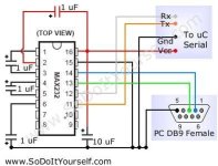
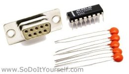
refering to level shifter/rs 232 interface, ur circuit is good, but for less noise and better interference protection why not register in maxim-ic website, and just order 2 sample max232 ic's for FREE?(not sure if samples are available, but worth trying). add some capacitors and voila.

Or better get max233 and u dont need capacitors.

circuit_232.jpg

max232.jpg

View attachment MAX220-MAX249.pdf
 
The caps are still needed (but only for the 232 - as I see you have mentioned - the other chip has built in charge pump -- RS232 standard is 10V signal max, caps act as a charge pump for return level matching) to be safe, unless your sure you have a 16550 or better UART or are using a IC based USB->RS232 adapter which is compatible with 5v and / or 3.3v signals.

While the max232 (and it's cousins) can be had for free and they do have less noise, etc... there is still a lag time before parts arrive and last I checked Radioshack offered no level shifter ICs suitable for the purpose, meanwhile...

If your in a pinch it's likely you have the needed NPN/PNP transistors (or their cousins which will substitute fine) and if not... you can run to radioshack in the US between 8am and 9pm and find those parts (outposts not included, they usually don't have much in parts) and in about 1/2 hour time have a working level shifter to program the infineon with.

Thanks though for the additional options... I hadn't thought to post up about the max232 - it would be a "cleaner" solution.

-Mike
 
Back
Top