
zukster
1 kW
nogas4me said:How many volts are needed on the small red wire to turn the 72v 45 amp controller on ?
Thanks
Why don't you just use your main power source?
nogas4me said:How many volts are needed on the small red wire to turn the 72v 45 amp controller on ?
Thanks
zukster said:Why don't you just use your main power source?nogas4me said:How many volts are needed on the small red wire to turn the 72v 45 amp controller on ?
Thanks
 pen the circuit.
zukster said:I'm just re-reading your info. Why is your keyswitch hooked up to a 60v dc converter? Can't
you just get one that is mechanical
on:close the circuit
off
The switch its self only has to be rated for a couple of amps I think. It also serves to more gently turn
on the battery voltage to the controller from the batteries.
There was some info on this circuit here too
http://endless-sphere.com/forums/viewtopic.php?f=2&t=9407

dnmun said:you really seem to not understand how the little red wire is there to carry the current to the voltage regulator which then delivers the 12V to the controller circuitry.
knuckles talks extensively about how to adjust the input power resistors to get the right size to use to protect the voltage regulator from voltages that are too high for it to handle.
you should go read all that so you can understand what is going on inside.
i think if you get to that level, then you will be able to see how to use the 12V output from your DCDC converter to drive the 12V rail inside and then you can figure out some way to manage the LVC signal from the R12 resistor bridge to the signal pin on the 846.
if you are using a lifepo4 pack with a BMS, there is no need for you to have controller level LVC if your controller current will be coming off the DC converter.
in that case you could build a resistor bridge from your 5V rail to drive the LVC signal pin on the 846 which would keep it turned on all the time, even though you would have removed all the high voltage that usually drives it through R12.
also you would remove the 12V LM317T regulator, and just use your 12V DC right to the caps on the 12V rail. should work ok.
or you can leave the LM317T in place since there will be nothing on it's high side.
), I just opened up the cable and its themwkeefer said:As far as I know not yet, I've played with probing the MCU but with no success.
Takemehome said:Found this on arduino forum.
SL …
(0: Switch Mode) When the “SL†contact point is “jumped†to ground (when SL is connected to ground) then the programmed value for “Limit Speed%†overrides the default “Speed 2%†setting. If the SL switch is opened (disconnected from ground) then the controller returns to the “Speed 2%†setting.
X1 …
(0: Switch Mode) When the “X1†contact point is “jumped†to ground then the programmed value for “Speed 1%†overrides the default “Speed 2%†setting. If the X1 switch is opened then the controller returns to the “Speed 2%†setting.
X2 …
(0: Switch Mode) When the “X2†contact point is “jumped†to ground then the programmed value for “Speed 3%†overrides the default “Speed 2%†setting. If the X2 switch is opened then the controller returns to the “Speed 2%†setting.
Julez said:Hello!......Low speed: This mode will be always on, also without pedelec sensor, to allow legal 6km/h.
Medium speed: This mode will be activated when the pedelec sensor kicks in, and allows legal 20km/h. Will overide "low speed mode".
Max speed: This mode will be activated by a hidden jumper, and by the pedelec sensor, and will override all other modes.
Getting to these 3 modes alone would not be a problem. The problem is how to make them override each other.
The manual says this:
SL …
(0: Switch Mode) When the “SL†contact point is “jumped†to ground (when SL is connected to ground) then the programmed value for “Limit Speed%†overrides the default “Speed 2%†setting. If the SL switch is opened (disconnected from ground) then the controller returns to the “Speed 2%†setting.
X1 …
(0: Switch Mode) When the “X1†contact point is “jumped†to ground then the programmed value for “Speed 1%†overrides the default “Speed 2%†setting. If the X1 switch is opened then the controller returns to the “Speed 2%†setting.
X2 …
(0: Switch Mode) When the “X2†contact point is “jumped†to ground then the programmed value for “Speed 3%†overrides the default “Speed 2%†setting. If the X2 switch is opened then the controller returns to the “Speed 2%†setting.
So, I could theoretically assign the "low speed mode" to the "Speed 2%" setting. So the bike will drive slow always. Then I could make the pedelec-sensor-driven reed relais connect "SL" to ground, thus allowing "Limit Speed%" to be activated. To this, my "medium speed" setting will be assigned.
Now, the big question is, how will I activate my "max speed" setting? When I assign this to “Speed 1%†and connect “X1†to ground as well, which setting will dominate? SL or X1?
Cheers,
Julez
Erikjan said:First sorry for my spell, English is not my first language.
I have a Lyen contoller 18fet Infineon. The controller is damaged. My fault.
Now I have received a new controller PCB and switch all the components that are not damaged.
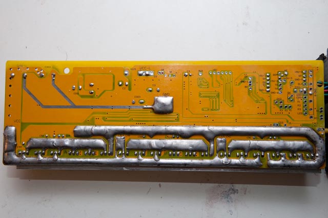
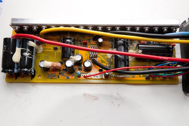
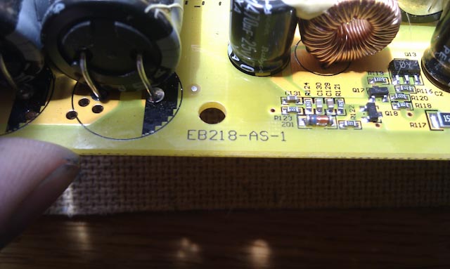
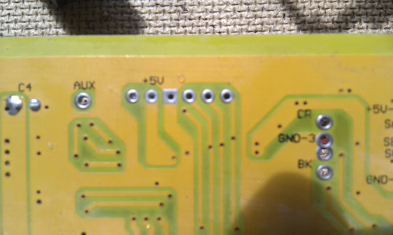
I have one problem the new PCB is a little different . This PCB have a coil the old one have big resistors and a voltage regulator. There are 3 components I don’t know the value. Can somebody tell me which value they are.
I need te now:
C003, CDG1 and R115.
*edit I find out the resistor R115 = 150 Ohm for 32-84V
*edit I find a pickture that shows CDG1 = 470Uf
The nr from the old PCB is EB218-A-4 The new PCB EB218-AS-1
Picture say more:
https://picasaweb.google.com/lh/photo/JK4Nd8vltKCe2qknO3ZoTdMTjNZETYmyPJy0liipFm0?feat=directlink