Is this safe or risky?

ebike11

1 MW
Joined
Nov 16, 2013
Messages
2,004
Location
far away
Hi guys
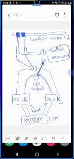
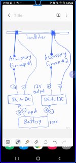
Im wiring a lot of accessories to (2) separate DC to DC 100v to 12v converters.
I am using 2 in order to share the load on the accessories. I have a horn, a lot of lights etc.

I also have 2 separate on/off switches on the handlebar

My question is, in the diagram I drew up, will the handlebar switch wires (which are very thin) make any difference when turning on and off the accessories? I decided to put the handlebar switch wires on the positive 12v side of the converters.
This is my main concern

Also would that be the appropriate place to put the turn on wires?

Hope you can follow my diagram.

Thanks!
 

Attachments

  • Screenshot_20211207-193943_Samsung Notes.jpg
    Screenshot_20211207-193943_Samsung Notes.jpg
    451.5 KB · Views: 587
I would not parallel two electronic voltage converters. They are switching regulators that could easily misbehave if the switching frequencies aren't synchronized. Even if they don't fail, they could fail to deliver the stable voltage your devices depend on.

Instead, divide your different 12V loads into two more or less balanced groups and assign them separately to the converters.

Since your handlebar switches aren't controlling relays, they must be able to withstand the entire current of whatever device they're connected to, including the inrush current for an inductive or capacitive load.
 
Chalo said:
if the switching frequencies aren't synchronized

Does it really matter given there are large output caps on both converters? I'd imagine that output voltage might even be more stable when perfectly unsynchronized. :lol:
 
Comrade said:
Chalo said:
if the switching frequencies aren't synchronized

Does it really matter given there are large output caps on both converters? I'd imagine that output voltage might even be more stable when perfectly unsynchronized. :lol:

Maybe? I know that a lot of these things are noisy enough to affect audio devices when they're not under load, and they'll surely become noisier as load and voltage ripple increase. You could smooth this ripple with more capacitance, but that's more capacitance to erode the switch contacts or plugs. What happens if the two are regulating to slightly different voltages? Simpler just to keep them separate. It's not like the OP is connecting a single high-power device.
 
Chalo said:
Simpler just to keep them separate.

Probably more efficient too since each one would have some quiescent current even when nothing is running.

2 small relays (controlled by handlebar) switching input of DC-DC converters is most optimum. But watch the caps on the converters for inrush so as to not damage the relays.
 
Where are your fuses (lboth in and out)?
I would just go with one DC-to-DC. Ensure current capability will handle combined max current of assessories.
 
Comrade said:
Does it really matter given there are large output caps on both converters?
Yes.

DC/DC converters are typically accurate to within about 2%. So a 12V converter will have an output of 11.75 to 12.25 volts. If one has an output of (say) 12.2 volts and the other is at 11.8 volts then the one at 12.2 volts will carry all the load.

What happens next depends on how it handles overloads. If it reduces power on overheat (ideal) then the other will start to pick up the load. But the higher voltage converter will always be overheating.

If it shuts down hard when it overheats, then the second one will see all the load and then it will overheat.

So bad idea unless the DC/DC converters are designed to share.
 
This doesn't make a lot of sense.

You drew two switches both feeding the same set of loads. That makes no sense, and will not help with loading. Perhaps you meant that each switch switches its own loads? If so then just separate the DC/DC converter outputs and all will be well.

Yes, thin wire matters. It's easy to calculate power/voltage loss in a given length of wire at a given load, so do the math.
 
Unless the buck converters are specifically designed to run with the outputs paralleled, then you should add diodes to the outputs before they are combined.
 
JackFlorey said:
This doesn't make a lot of sense.

You drew two switches both feeding the same set of loads. That makes no sense, and will not help with loading. Perhaps you meant that each switch switches its own loads? If so then just separate the DC/DC converter outputs and all will be well.

Yes, thin wire matters. It's easy to calculate power/voltage loss in a given length of wire at a given load, so do the math.

Yes I meant that each switch will turn off its own converter.
The load on the switch wires would only be 12V or so since its on the outpit side, so shoukdnt the thin wire be able to handle that voltage??
 
pullin-gs said:
Where are your fuses (lboth in and out)?
I would just go with one DC-to-DC. Ensure current capability will handle combined max current of assessories.

I agree..but i had already 2 x 100to12V of the same converters so im trying to use those at the moment
 
E-HP said:
Unless the buck converters are specifically designed to run with the outputs paralleled, then you should add diodes to the outputs before they are combined.

These converters only have 3 wires each. 1 ground 1 input and 1 output. The black ground is for both input and output
 
How about this way??..both switchs are independently turning on and off its own converter and the converters are independently wired directly to the battery positiv and negative. Though they are sharing the same battery +/- wires.
 

Attachments

  • Screenshot_20211209-145801_Samsung Notes.jpg
    Screenshot_20211209-145801_Samsung Notes.jpg
    457.7 KB · Views: 504
ebike11 said:
How about this way??..both switchs are independently turning on and off its own converter and the converters are independently wired directly to the battery positiv and negative. Though they are sharing the same battery +/- wires.

How much energy do those converters suck? Could be several watts while idling. Higher voltage = less current for given power. Your switch really should be on the battery<-->converter side if there are thin wires. Less energy loss in that case. But then again, bringing 100V to the handlebar is not good idea. You should put a relay between the battery<-->converter and switch them from the handlebar.
 
ebike11 said:
How about this way??..both switchs are independently turning on and off its own converter and the converters are independently wired directly to the battery positiv and negative. Though they are sharing the same battery +/- wires.
Yes, that's better. Now add some low amperage fusing on + output of each converter to protect your devices and the wiring. Your converters can pass a lot more amperage than your handlebar wiring can handle. I'd also go through all the handlebar and new device wiring and make sure all the connections are clean and tight.
 
ebike11 said:
Yes I meant that each switch will turn off its own converter.
Great, that's better.
The load on the switch wires would only be 12V or so since its on the outpit side, so shoukdnt the thin wire be able to handle that voltage??

The amount of CURRENT a wire can handle depends on how much COPPER it has (i.e. how heavy it is.)
The amount of VOLTAGE a wire can protect you from depends on the quality and thickness of the INSULATION.

Two very different things.

In your drawing, the battery wires carry higher voltage and lower current. On the output side, they carry lower voltage and higher current. Ensure that you 1) use fuses any place a wire might be overloaded by its source and 2) that all the wires are thick enough gauge to carry the current you want to carry. At the voltages we work at, insulation is usually not an issue, as long as it is not damaged and all connections are insulated.
 
Those buck converters are not isolated devices more than likely. Who knows what quality your handlebar switches are. A bicycle is a wet environment potentially. 100V DC is no joke if a set of events come together. Try licking the terminals on your battery if you don't believe me. :mrgreen:

You should Google "death from USB charger". You are dealing with cheap Chinese products, high voltages, and DIY'ing with not a lot of electrical experience.
 
You'll want a contactor or other master cutoff on the battery, so the voltage converters don't dribble away your charge during periods of disuse. But you definitely don't want to switch the accessories on and off from the 100V side of the circuit, because that will quickly wreck the switches by spark erosion.
 
Risky but could be safe
Low voltage for safety to the handlebars is critical
Low current for thin wires to the handlebars avoids lots of voltage drop at high current
I'd suggest 2x 20A 12V relays controlled by one handlebar switch and a manual 100V switch to avoid battery drain
A BMS might do the high V remotely and safely or a carerully wired appropriate outdoor spec mains power switch (16A 110V) should be ok.
There is no problem switching 5A at 100V if you have the right switch, domestic switches handle this every day but it doesn't mean that one from ebay for ebikes will work. Ditto 20A at 12V if the switch isn't rated for it - check the spec.
A single handlebar switch can control both relays, each relay can supply its own set of components reducing wiring to handlebars
Short thick wires for the 2X 40A at 12V dependent on the load
Several thinner ones in parallel to individual devices will work
A 20A fuse for each buck converter output and one for the inputs near the battery will protect the wires and battery from short circuits which can be terminal.
I tend to harvest old automotive relays from the fusebox of cars in the scrap yards Grab 20, and pay a dollar or two to the chap at the gate. Easy connection with spade terminals, lots of circuits you can build with relays (basic logic gates)
It also depends on what you want from the handlebar switch, eg if you need multiple switches
Just my 2c
 
BobBob said:
There is no problem switching 5A at 100V if you have the right switch, domestic switches handle this every day

Those are AC switches. That's a much easier job, to the point that a 120VAC switch may only be rated for 12VDC. DC doesn't have any zero crossings to extinguish the arc and let the switch fully close.
 
Chalo said:
BobBob said:
There is no problem switching 5A at 100V if you have the right switch, domestic switches handle this every day

Those are AC switches. That's a much easier job, to the point that a 120VAC switch may only be rated for 12VDC. DC doesn't have any zero crossings to extinguish the arc and let the switch fully close.
True, you need to read the spec sheet on the switch and ensure it can take the load and DC rated are more rare
I don't know whether the peak current and voltage being higher makes much of a difference vs the zero switching
The first example industrial breaker type switch I found has the same rating for AC as DC though this is not a domestic switch
https://uk.rs-online.com/web/p/non-fused-switch-disconnectors/8055572
I was going to mention that Solid state relays tend to be AC zero switching and won't work either
I'd also be worried about a handlebar switch with 20A going through it, high current is not good from them either
Wire gauge recommendations for 20A also range from around 9 AWG to 16 AWG that I've found
 
BobBob said:
Wire gauge recommendations for 20A also range from around 9 AWG to 16 AWG that I've found

9ga? Maybe if your wire is a mile long or something. For a wire no longer than a bike, 16ga is plenty big enough to carry 20A all day.
 
Chalo said:
BobBob said:
Wire gauge recommendations for 20A also range from around 9 AWG to 16 AWG that I've found

9ga? Maybe if your wire is a mile long or something. For a wire no longer than a bike, 16ga is plenty big enough to carry 20A all day.
Sure, that example was extreme, it's an illustration of the variation in advice you can find on Google and depends on application.
I've put 1500A though 8Ga for a few ms :)
Some discussion here https://www.rcgroups.com/forums/showthread.php?198178-Wire-thickness
Saying that the switch and wire need to be appropriate for the job and a long chunky wire is probably less of a good idea than a relay IMO
Edit :
Might suggest going to 14 Ga
16 Ga wire at 14 mΩ / m and two circuits looping to the handlebars and back, each with 20A could be:
2 x 20A x 14 mΩ/m X 2metres = 0.56Volts lost X 40A = 23Watts lost or around 5% of that used by the PSU assuming all connectors and switches are perfect
If this is the solution chosen, test for voltage drop and make sure it's not much worse than this.
 
Chalo said:
But you definitely don't want to switch the accessories on and off from the 100V side of the circuit, because that will quickly wreck the switches by spark erosion.

No matter what method is used to power on the step down buck converters, they very likely have large caps on the input and very likely have no inrush current limiting of any kind since they are built to be as cheap as possible. They will need an NTC on the inputs no matter what.
 
Back
Top