JD's VW Bus Conversion EV project (2 of 2)

Unless you are giving basketball players a ride in the back, your battery mounting location is perfect. With a good stout plywood top, you could still carry a cord of firewood in there. Another option is the way I had my bus set up. All seats removed, and a plywood platform built to make a bed length with about 2 feet of space left behind the seats. Under the plywood was a ton of space on the floor, still very forward, where a big load of batteries would fit. In a pinch, people could sit on the front edge of the bed. Dogs loved it, and it was really nice for carrying long items like lumber or sheets of plywood. Under the car will be difficult to seal for water and you have lots of space inside. To boost range just a few miles, maybe a 2000 watt generator would fit in the engine bay? Not to use all the time, but for those occasional trips a couple miles past your range? Be nice to be able to go somewhere and have the car recharge while you go for a hike or ride.
 
The one thing I have been wondering is about rear weight. But since I have only worked on a couple of VW buses I'm not a 100% sure. It seems considering the suspension, one needs a certain amount of weight similar to the weight of the original motor, otherwise the camber on the rear tires will not be correct. Since I have never done an alignment on such vehicle, I'm not sure how much adjustment there is. Also if the bus is too high at the rear, the driveshafts will be at high angle, wich is never good for universal joints, not to mention exessive tire wear if camber is out.

Since I have very little experience on this vehicle, I'm not sure of my claim, but I figure I throw it out there just in case. I know right now just getting things running is of major concern, so things that I mentioned are not even thought of at this point.

Keep up the good work.

Roy
 
That model should be able to ride real high and not affect camber any. The old swing arm ones would have that problem, but fixable by pulling out the torsion bars and setting em one notch lower. The newer ones adjust the same way, but the cv driveshafts let the wheel stay aligned regardless of height so he shouldn't need to do anything.
 
Ok thats answers my question, I knew that VW front ends had trailing arm suspension, but since I know little about busses, wasnt sure about the rear end of buses, sorry about that.

Roy
 
Here's where I'm ignorant, but the electric motor could quite possibly weigh almost as much as the gas one did. They look small in a pic, and then you put a hand or something in there and wow, thats a big elecric motor! In you mind, you sorta want it to be like something familiar, like a starter motor. With a motor out, they will jack up pretty high though.
 
Eric, thanks for the good words, and ya know what? On an aircooled vw, it actually IS easy, simple bolt on. Lots of figuring out what to use and where to put stuff, but the actually assembly isn't that challanging (if you mind the hazards).

Gary, thanks for that training session, you filled in several knowledge gaps for me. I was able to tweak half of the subchargers in the Vicor PSU up to 57v, for 3.56 a cell. They trim down to 30v, so I could have series both halves of it into 60v, but 3.75v is a little higher than I want to go with these cells just yet. I'm not currently in danger of draining them enough for balancing to be an issue, but when I get it more roadworthy and add more cells, it will be easy to trim from 60 to 114v and I will shoot for 3.65/cell.

BTW, the single-cell vicors I got weren't the 3.7v 4.2a supplies, they are 48v to 3.7v/20a DC-DC converters. 20w loss on the conversion (22%) is a bit much for regular charging, but they ought to make nice balancers.

Dogman, sounds like a good bed design you had, and would be perfect for a lead-acid conversion that needs tons of space. This one has a 'Z-Bed' rear seat - it folds flat and raises up to the height of the cushion in the back, making a nice big bed, otherwise I'd follow your lead. Thanks for chiming in about the rear camber - I didn't think it would be an issue, but you explained it better than I could have.

Roy, thanks for looking out for me! I'm still considering your carb cleaner suggestion on my Comuta-Car project, I got some PB blaster to try first but I haven't been able to get back to that project for a while.

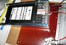
Anyhow, I've been exhausted the past two nights and done very little, so all I have to post is a pic of the Vicor charging away.

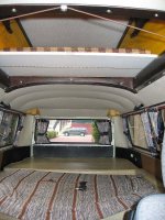
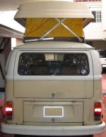
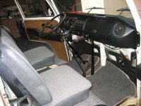
Hmm... I'm also gonna add some pics from 3-4 years ago when the bus was cleaner and less damaged by sap and the elements... I redid the front seats and carpeting, these photos show them nicely. After the conversion it would nice to redo the Z-Bed and back pad too.

-JD

EDIT 12/14/12: replaced pictures lost when the forum crashed a few years ago.

vicor charging_5812.JPG
View attachment 4
b_popped_both_beds.jpg
b_popped_open.jpg
b_popped_back.jpg
b_i_dash_pass.jpg
 
oatnet said:
BTW, the single-cell vicors I got weren't the 3.7v 4.2a supplies, they are 48v to 3.7v/20a DC-DC converters. 20w loss on the conversion (22%) is a bit much for regular charging, but they ought to make nice balancers.

Actually, I just bought a bunch of these 3.7V/20A supplies from Bill as well. :) You are right, they will be great for topping of the cells, and making sure all the cells get a full charge.

One other thing you might consider eventually adding is a cell-level LVC board that will trip a controller input to cut the throttle if any one block of cells dips too low. I know you plan on not discharging below like 20%, but why I think it is still important is that if a cell does go bad, the problem is that it will try and drag down the other cells in parallel with it, so you could end up with a whole bank of dead cells.

Anyway, looking forward to watching this progress. :)

-- Gary
 
GGoodrum said:
One other thing you might consider eventually adding is a cell-level LVC board that will trip a controller input to cut the throttle if any one block of cells dips too low. I know you plan on not discharging below like 20%, but why I think it is still important is that if a cell does go bad, the problem is that it will try and drag down the other cells in parallel with it, so you could end up with a whole bank of dead cells.

I've been watching your LVC development on and off for a while, when I get there I'll want your boards protecting my cells. I'd probably wire it up to a relay driving an annoying alarm instead of the brake line - there are places where I'd rather burn a supercell than be disabled, can't pedal it like an ebike <grin>. Guess I could wire an override switch just as easy as the alarm, but oh that sinking feeling when you are slapping the accellerator and nothing is happening - with an alarm I'd know what was wrong right away.

I had a fantasy of building a basic-stamp or propeller-chip project to track voltages of all the supercells and list them on a simple text display. With that I could also do a balancing alarm on a cell when it reaches a delta off the average of all cell voltages - that would warn just a little sooner than LVC. However, there are so many priorities on the list before that I should probably forget it.

Today I bought an aluminum sheet to permanently mount the controller, and a sheet of Phenolic plastic to cover the sheet everywhere but the controller's base. Phenolic is probably overkill, but i'd hate to have a battery cable shake loose and drop onto bare metal.

eric said:
Have you considered the potential need for battery (or motor) cooling?
Are you going to include a rain or dust shield underneath the motor?

My current setup handles battery cooling very well, but it is a concern for when I stack rows of supercells in the gas tank area. Motor cooling is a SERIOUS concern on VWs, because the motor is mounted "backwards" of a typical EV. This means the built-in fan on the forces air back to front, against the wind. EV Source offers a shroud and blower that I am considering: http://www.evsource.com/tls_motor_accessories.php The bus also has scoops up high on the sides that are designed to force cooling air over the ICE, but I'd I have do design new shrouds to get the air to the motor. There is a thermister built into the motor, the controller will cut back if I am overheating, so I'll work the problem if I get there.

I have considered covering the entire bottom of the bus with coroplast or something, to reduce drag. Rain is not much of an issue in SoCal - well I guess right now lack of rain is. To realistically protect the motor, I'd have to wrap it in a box, the Bus engine bay is so open.

dogman said:
Here's where I'm ignorant, but the electric motor could quite possibly weigh almost as much as the gas one did.
To boost range just a few miles, maybe a 2000 watt generator would fit in the engine bay?

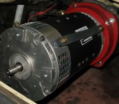
This 9" motor weighs 143 lbs on the ADC spec sheet. The ICE allegedly weighed 275lbs. The gas tank sat directly over the rear wheels (@125lbs full).

I did consider leaving the tank in place, and using it to fuel a generator on each side, so I could call it a hybrid :D . Then I remembered my weight target and got over it. I need to buy a generator in case I get stranded (1200w will fully power the vicor!) but I'll only bring it out (or my wife will :lol: ) if I get stranded and can't get a convenience charge.

-JD
 
I need advice -

I know diddly about getting metalwork done. I need to have a mount made to support the back of the motor. I have two convenient hard points on either side of the motor, where the "moustache bar" that supported the ICE was bolted on. I'd like to get a bar made that uses those hard points, and is welded to a flat plate with a hole for the tailshaft, and screw holes for the motor faceplate, er butt-plate.

What kind of shop should I look for to do this kind of work? What would be a reasonable cost? How does one commission this kind of job, just walk in and point at my bus?

-JD

PS - Would I be whacky if I mounted an etek-pattern PM motor in parallel with the tailshaft, and used it for regen? i could just make the mounting plate taller with Etek cutouts... I haven't researched a clutch/pully that would make this viable without parasitic cogging from the PM, but it has been in the back of my mind, I have ajust such a motor, and now would be the time to at least make the space...
 
Make a mock up out of cardboard of the mount you need made out of tube stock or angle iorn. Take it to any welding or iornwork shop. The less they have to measure and design the cheaper it will be for you with no shop time on design. Monitor the motor temp with an indoor outdoor thermometer. Cheap at car parts places, the sensor can be mounted to the motor case where it gets hottest and the wire lengthened to the dash. If you seal off the bottom of the engine bay, you can then controll the air flow to the motor. A cheap but ugly scoop can be made of dryer vent, as you know from the other guys video. The vent could direct colder air to the motor intake area with flex duct. While the car is not moving should not be an issue, the motor is still. :D Wish I had some money, I just found a rabbit pickup for sale cheap. Perfect for an EV. So much time, so little money, don't do the dope anymore to get through it.
 
I would bolt together a beam from square tube. Gives you lots of options on revisions.

You could also explore "universal" or "multi-fit" trailer hitch framework...
 

Attachments

  • 37010_2.jpg
    11.4 KB · Views: 4,737
That's true, some square tube, a few bolts, a piece or two of angle iron..... Maybe no need to weld at all. Just use good grade 8 bolts.
 
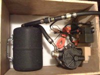
booster_0842.jpgWorking hard, I haven't had a chance to post.

Above is the vacuum booster assembly for the brakes I completed a few nights back. It is mounted in the wood box that I got my 10ah cells from Andy/Falcon Ev during the 2007 Alt-Car-Expo, fresh off the boat from Taiwan. I think these are the same cells Justin at ebikes.ca is selling, they have served me well.

On the lower right is the actual pump and oil-filled muffler. The black cylinder on the left is the vacuum reservoir, on the hose is a check valve (left) and the vacuum sensor. Mounted to the left wall are the relays that monitor the sensor and turn on the vacuum pump.

I bought this kit from http://www.evsource.com/tls_braking_system.php for $366 delivered. Noise is reported to be a concern with these pumps, and this is touted as being quiet. I powered it up briefly and it did run quietly, though it sucked so much juice that it melted my test leads. I look forward to mounting this, I'll have to see how much juice it consumes, I may not have budgeted power adequately for it.

========================================

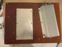
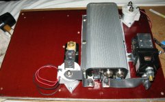
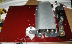
I bought the 20" x 14.75" x .375" aluminum sheet (seen below) on ebay for only $37 shipped. I also got a 16 "x 48" x 0.060" sheet of Phenolic plastic from the same vendor, both local to me so GREEN shipping.
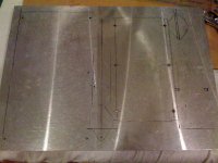
1-predrilled_0851.jpg
2-test-mounted_0852.jpg
3-phenolic-0853.jpg
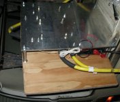
4-finished-_5870.JPG

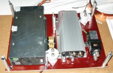
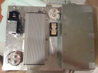
On the left is a Vicor Power supply. I bought this CHEAP when Doc Bass recommended them a ways back, but never used it - and now the mount that came with it is very handy! I am actually using a different vicor PSU than the one in the picture, but this is good for a test mount.

The Vicor's come with slots for (8) independant PSU that can be any combination of v/a, combined in series or parallel. I will fill (6) slots filled with 48v4.2a PSUs to charge the main pack. These can each be trimmed from 30v to 57v, giving me all sorts of combinations. For example:

I can parallel (4) of them to charge my 48v80ah pack at 16.8a, @0.2c.
I can do 3p2s to charge my future 96v80ah pack 12.6a.
I can do 2p3s to charge a potential 144v80ah pack at 8.4ah (@0.1c)

The remaining 2 slots I have filled with 12v 4.2a PSU that I will use to
a) charge the 12v pack that runs the brake booster, accessories, controller logic etc,
b) drive the EV200 contactor in the upper right, that closes the circuit on 48v-180v main-pack charger so that line is only active when the PSU is on.
c) open a relay that breaks the circuit on one of the motor-power contactors, so that if the charger is on, I can't power the motor.

Elegant, eh?

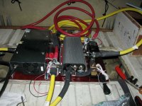
So the rest of the stuff... The Kelly KDH14500B controller is pretty obvious. On the left of it is the 500a/50ma shunt where I will land the 4/0 cable that supplies V+ from the battery. That will connect to the white EV200 Contactor in front of it via copper strap. This contactor's actuator leads will be hooked to an emergency cutoff switch up front. The 4/0 cable to S1 will connect to the other side of the contactor, as well as a copper strap that connects to the controller's B+ spade. The Controller's B- contactor will connect to the 600a kelly contactor on the left, which will be activated by the ignition.

I figured a mix of contactors would be good, something that kills one might not damage the other. Although the aluminum plate is needed to cool the controller (and a handy sturdy mounting platform), all that exposed conductive metal was making me nervous, that's why I put down the phenolic plastic with a hole cut out for the controller.

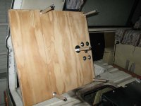
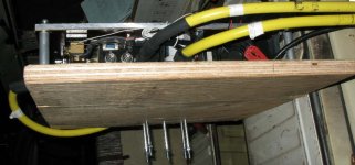
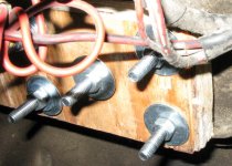
Oh, also note the 5 aluminum tubes/steel bolts in the corner and center. I am going to use them to mount a 1" plywood sheet to the assembly. This whole assembly will then flip over (wood side down) so that if it is ever accidentally exposed to water, it will drip down to the wood instead of pooling. I will also mount the throttle assembly/secondary return spring to this piece of wood, the subject of future photos.

Ah, the throttle. Friggen Fernando also CLIPPED my friggen throttle cable, so I don't have much to work with. Arg.

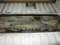
Anyhow, next I have to clean the engine bay, use the copper strip in the picture above to make laminated straps to connect the contactors/shunt/controller, make another laminated copper strap to connect S2/A2 on the motor... Then some wiring, and the whole mess goes into the bus with the brake vacuum pump and I should finally have reasonable control of it. Last bits will be to run an armoured casing with a bundle of wires to the front to connect my JUMBO CycleAnayst, and some control bits (emergency cutoff, brake sensor, etc) and the conversion will be complete - well, until I add more batteries that is.

Then I have to replace the burned wiring to the taillights etc and I can power up the bus's main 12v system for lights and signals. Then I have to repair a torn cv boot. Ah shoot, I forgot about the motor mount.

EDIT 12/14/12: replaced pictures lost when the forum crashed a few years ago.
 
JD
I'm impressed with the progress you've made on this project in such a short time. I'm in the late planning stage of a conversion myself and a little daunted by the work ahead so it's great to read your detailed record and see all the pieces coming together.
I have a question though. I see you have three contactors – two Kilovac EV200 and an Albright. Most people seem to recommend one on the positive side and another on the negative side so that you can completely isolate the pack, but what's the third one for? Is it just added redundancy? Nothing wrong with that of course, I'm just curious.

You've packaged brake servo pump very neatly there. I realise that's partly to muffle noise from the pump and you've probably already thought this through, but isn't there a risk the pump could overheat inside that box if it draws a lot of power?
 
Malcolm said:
JD
I'm impressed with the progress you've made on this project in such a short time. I'm in the late planning stage of a conversion myself and a little daunted by the work ahead so it's great to read your detailed record and see all the pieces coming together.
I have a question though. I see you have three contactors – two Kilovac EV200 and an Albright. Most people seem to recommend one on the positive side and another on the negative side so that you can completely isolate the pack, but what's the third one for? Is it just added redundancy? Nothing wrong with that of course, I'm just curious.

You've packaged brake servo pump very neatly there. I realise that's partly to muffle noise from the pump and you've probably already thought this through, but isn't there a risk the pump could overheat inside that box if it draws a lot of power?

Hi Malcom!

Thanks for the good words!

I fully understand the 'daunted' bit - looking at the total job is stressful, but breaking it into subtasks - "today I am gonna complete xxxx" helps a little bit. Honestly, each of these subtasks has proven doable with my limited skills. Taking an intemediary stop of mounting things roughly/quickly, seeing it work, and remounting them as I now see I need them, has been a big help. I don't need to anticipate everything and get things perfect the first time, because I'll figure it out in the next design; I don't need to worry about reworking something I spent a lot of time on, because the first build is so crappy that I know I am going to have to anyhow. :lol:

Good point about the pump. This was a nice modular way to package it, until I decide a better mounting would help. I have seen a few boxed installs (of different kits :shock: ), and didn't give it another thought. Open to the top, heat rises... I'll have to monitor it and see. Hopefully I find the run time is intermittent enough that it doesn't suck juice and doesn't heat up.

The 'Albright' contactor is actually a 600a (12v coil) $89 from Kelly:
https://www.kellycontroller.com/shop/?mod=product&cat_id=12,28&product_id=456

The third contactor (back right) is for the charging circuit, not the motor power circuit. From the Vicor PSU, I'll run the positive charging wire to the back of the shunt, and the negative charging wire to that third EV200. The other side of the third ev200 will connect to the Kelly Contactor (battery side). Without the 3rd contactor, this circuit would be 'hot' to the battery all the time, a hazard at worst and a potential battery drain at best.

In addition to the 48v-180v charging output, the Vicor has a 12v output that I will use to drive the 3rd contactor. When the vicor it is powered on to charge, it automatically activates the 3rd contactor, which completes the charging circuit. If the PSU gets fried, the 3rd contactor loses power and breaks the connection. An ev200 is probably overkill for the load, but they are rock-solid, cost me only $63 new, and I had a spare (originally intended for my Comuta).

Oh, I am also planning to have that vicor 12v circuit power a normally-closed relay, and put that on the circuit that drives the Kelly contactor's coil - so when the vicor is powered on, the NC relay breaks the Kelly's coil circuit, and the Kelly Contactor breaks the motor power circuit. Effectively, the contactors/relay will swap out the controller and the PSU on the battery circuit so they are never connected at the same time. That way I con't forget it is plugged in and drive away. :shock: :roll:

While pack isolation is a nice by-product, I am using (2) contactors on the motor power circuit for redundancy and diversity. The coil electronics on the ev 200 are nicely contained, almost waterproof, but when used at 500a levels you are supposed to have it connected to 4/0 cables to dissipate heat so I gather that might be beyond its design usage. The Kelly contactor is not hermetically sealed, but it is a big beefy beast built to handle 600a. (I also bought their $69 400a version for use on my Comuta-Car project, which is identical save for smaller contact points) So if water exposure kills the Kelly, I can bypass it and limp home on the ev200. If the ev200 gets smoked by the load, I can bypass it and limp home on the Kelly. If the controller fails full-open (and the fuses do not blow?), hopefully one or the other will be able to break the circuit.

-JD
 
Sounds like you've got every angle covered. I didn't know that about the EV200 needing additional heat sinking when handling higher currents. I just picked up a couple of them myself, so I'd better read the data sheet... I'd guess they're talking about 500A continuous though, so there should be some headroom there.
 
voicecoils said:
oatnet said:
Can anyone tell me, if I put my multimeter on the ends of an individual cell, will I read the voltage of that cell, or the voltage of the entire supercell?
Yes, you can measure the potential (voltage) across any individual cell, regardless of how it is connected to other cells. Just jump in with a multimeter.

You can also charge or discharge any individual cell in the same fashion, while connected to the others. The circuit (say the multi-meter with probes on each end of one cell) is only 'closed' around that cell, so that's all it sees.

Hey voicecoils - FYI I knew this answer didn't fit with my parallel charging experiences, so I asked the question again on another thread, and I got the opposite answer from Fechter:

http://endless-sphere.com/forums/viewtopic.php?f=14&t=8733&p=133209#p133204

-JD
 
Malcolm said:
Sounds like you've got every angle covered.

I drove myself NUTS considering angles when I was in the design phase. :roll: Unlike an ebike pack that I can rip off the frame, If something goes wrong, the whole bus could go up. I tried to consider what was in any way possible - if I wanted to sabatouge the system, how could I do it, and how could I design the system to recover from it? In my ignorance, I have probably attempted to cover far more angles than are likely to occur, I just hope I haven't missed any critical ones! :shock: :oops: :D .

Malcolm said:
I didn't know that about the EV200 needing additional heat sinking when handling higher currents. I just picked up a couple of them myself, so I'd better read the data sheet... I'd guess they're talking about 500A continuous though, so there should be some headroom there.

Yeah, 500a continious should far exceed my loads. Since I have read that brushed controllers fail open (full battery current!) I also think about them handling/breaking that load (mfr says it will break 2000a once). Of course, one of the silicon fuses _should_ blow at that point, but I have made a career of underestimating shoulds. :lol:

Anyhow, the source of my rumor-mongering about the 4/0 cables: http://www.evsource.com/tls_relays.php
"4/0 Cable connection(s) made to the terminals of the contactor to help dissipate heat from the internal contacts
Battery current limited to 500A or less"

Datasheet:
http://www.evsource.com/datasheets/tyco/EV200_ds.pdf

-JD
 
JD, i would suggest an independent muffler shop to help you make a brace for the back end of your motor. they can make brackets to bolt onto the frame and then bend tubing and cut it to weld onto the bracket plates so your brace would be removable. maybe wait and figure the big picture about the remaining stuff, like the heating ducts running forward, useless gas tank, and the useless starter or other stuff still there and where you may need to run your cooling ducts, or place the batteries or controller, and then let them fabricate something for you while on the lift. this means you will have to be comfortable with standing there and telling them how to do it while it is on the lift and the big problem is finding someone who will let you even be on the shop floor much less under the lift. think discount mufflers who take cash but still can speak enuff english to get the job done, but you can do a lot of it yourself (communicating) with sketches and cardboard mockups on the spot
 
I am on 'vacation' this week so I have been busting my hump on the bus from 7:00 am to 9:00 pm - lots of work, took me lots longer than I expected, but well here it is:

EDIT 12/14/12: replaced pictures lost when the forum crashed a few years ago.

0-copper strap and thermistor_5898.JPG

1-oops_5879.JPG

2-fixed_5880.JPG

3-vicor_5881.JPG

View attachment 2

5-the hole_5884.JPG

6 ready for board_5885.JPG
 
View attachment 5

8-top of board_5887.JPG

9-controller mounted to board_5888.JPG

a10-more controller mounted to board_5889.JPG

View attachment 1

a12-underside mounting_5897.JPG


Weight I removed:

- Engine/exhaust - 275 lbs
- 12 gallons of gas: 96 lbs
- Gas tank - 20 lbs
- 12v Pb battery - 22 lbs

- 413 lbs so far

-(future) starter/solonoids - 25 lbs
-(future) Fuel pump and fittings - 15 lbs
-(future) Asst heating system parts - 15 lbs

Weight of the parts I put in:

+ The aluminum plate weighed 11 pounds, and with everything mounted to it (Vicor, Controller, contactors, and wiring) it weighs 36.8 lbs
+ The 4/0 cables (2x 14', 2x 4') weigh 27.6 lbs
+ The mounting board, mounting bolts, and riser tube assemblies weighs 11.2 lbs
+ The motor weights 143 lbs.
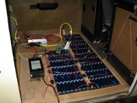
+ The 128 batteries weigh .75lb each, so 96lb total.

That is 314.6 lbs total so far; when I add in (14) more supercells to fill the battery tray that will be 84 more lbs, 398.6lbs.

+Oops, haven't weighed the vacuum booster yet. That will add weight, but I'll easily still be lighter than stock.

I'll have to add the motor mount to the tally, when I get it made, and compare that to the Moustache bar (30lbs) that suported the ICE and is not included above, I expect to reduce weight there.

Things not added: I don't know how much the wood in the battery tray weighs. I did not weigh the fuses, supercell joiners, or the copper straps at the ends and between the rows, or the S2-A2 copper strap on the motor.

OTOH, there were a lot of misc parts that came out, all of the tin (airflow guide), tons of little random parts.

So my bus, at 90v, will definitely weigh less than it did with the ICE. I wonder how a it will perform compared to a 144v Lead-Acid Conversion that adds 1500 lbs to the stock weight... That is the ultimate answer I am looking for in this experiment.

Still to come:

Throttle
J1/J2 wiring harness
Vacuum booster - i need to convert 3/8" to 1/2" - arg.
Maiden Voyage!

-JD

EDIT 12/14/12: replaced pictures lost when the forum crashed a few years ago.
 
Nice work Oatnet!!

Lucky you are to realize that project!! i'm still on two wheels :lol:

i'm following your project !

Doc
 
Wow looks good can't wait to see the maiden voyage. Got to admire a guy who goes on vacation so he can work his ass off on an EV project.
Mark
 
markcycle said:
Wow looks good can't wait to see the maiden voyage.

Mark, your wish is my command!

I got an inner ear infection on that last day of work, haven't been able to get near it to solder the last three wires until today...

On the maiden voyage, I didn't want to go very fast because the brake booster isn't hooked up yet (I need a 3/8" to 1/2" hose adaptor) and until I repair the burned wiring on the taillights I can't hook up main system power - brake lights, turnsignals, etc.

Changing gears was easy - THE CLUTCH WORKS without a pilot bearing! It pulls away in first gear better than the old ICE did, but it felt like it was running out of ooophm at the magic 25mph mark. OTOH the ICE was slow to build speed too, and I didn't take the time to push it faster without vacuum assist for the brakes.

After making the video, I also soldered up my Jumbo Cycleanalyst, now I finally have access to the information I am used to, the data I need to see how the batteries perform. I think I'm just gonna talk to Victoria and get another batch of cells now, and take it up to 96v since I already have space in the battery tray. I have a feeling I'll get another batch after that and bump it up to 144v... then 180v... :lol:

TD, you were right - it was darn near silent inside. I was suprised to hear how loud it was in the video, but I think that is just tranny noise.

It's short, but so is life so enjoy!

-JD

[youtube]PtT_Ju1SI0Q[/youtube]
 
Back
Top