Greetings ES... Some of you might know me from DIYElectricCar; to the rest of you I apologize in advance.
flangefrog said:
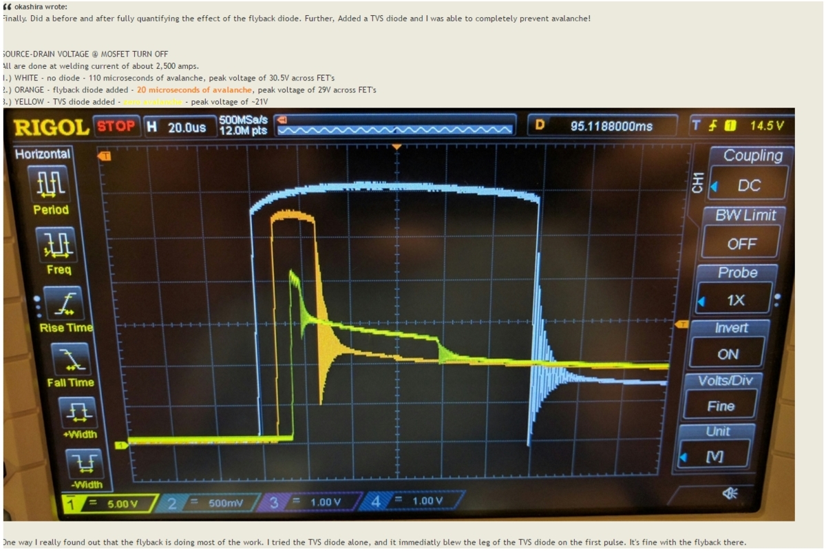
Avalanche current
In an effort to understand exactly what avalanche currents can be sustained without destroying the mosfets I've been looking at the Typical Avalanche Current vs. Pulsewidth figures in the mosfet datasheets. The mosfets I mentioned in my earlier post all have a 200A avalanche current rating for a single pulse of 100us when starting at 25C junction temperature and with an allowable rise of 150C. Change the pulse width to 110us which is what okashira was getting and it goes down to about 110A or 120A for the IRF1324PbF.
...
Have I been reading the figures and applying the values to our specific application correctly?
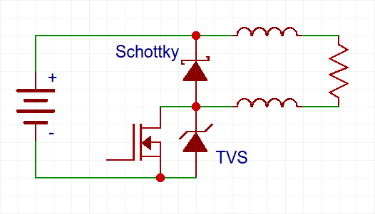
Firstly, you don't want to avalanche FETs unless your goal is to create extremely fast transitions and/or lots of ringing - the appropriate solution is to use a freewheeling (or flyback) diode from the FET drain(s) to the positive rail (which needs to be decoupled with a decent amount of capacitance). Note that there must be as little inductance as possible in the loop between the input capacitance, the switch and the freewheeling diode to prevent overshoot/ringing during switch turn-off, and the freewheeling diode should be a Schottky type with a "single pulse" surge current rating higher than the expected peak current during welding, though the average current through it will be very low.
That said, if you already have one of these gadgets without a freewheeling diode then there is usually a spec in switching transistor datasheets for allowable avalanche energy (and if you are lucky it will state values for both single and multiple pulses with a duty cycle for the latter). And the amount of energy that needs to be handled during avalanche is described by the equation 0.5LI², where L is the total inductance of the welding cables (and of the positive battery cable(s), too, if there is no decoupling/input capacitance [hence why you need such]!) and I² is the peak welding current.
Inductance of a wire in free space is about 8-10nH/cm, so there won't be much here - probably about 1-2uH total - but the weld current is, of course, quite high and probably not knowable ahead of time as it depends on battery state of charge and all the various resistances in the circuit.
But let's say you have 1uH of stray inductance and 2000A of weld current; that gives you 2J (Joules) of energy stored in the stray inductance. If there isn't a path for this energy to freewheel it will create one, by causing an overvoltage breakdown of the FET (aka - an avalanche). Hence the FET(s) need to be capable of handling more than 2J of avalanche energy.
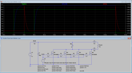
Attached below is a screenshot of a quick simulation of this circuit in LTSpice. The green trace shows the gate drive signal (1ms on, 1ms off, 8ms on, 1ms off); transition time is 10ns. The blue trace shows weld current - the rather lazy rise and fall time is the result of the L/R time constant formed by the total loop resistance and the cable inductance. Finally, the red trace shows the current through the freewheeling diode - and which more clearly illustrates why I only put one diode on the schematic...
The IRFH6200 FET is a reasonable choice, but I mainly selected it because it is one of LTSpice's default components, not because it is ideal for the job. If you look up its datasheet it says it can handle 780mJ of avalanche energy (ie - 0.78J) so 4 of them in parallel would be okay without the freewheeling diode as long as weld current is below ~2500A. Similarly, I didn't even bother with picking a specific freewheeling diode, mainly because the Spice primitive is good enough here.
Which reminds me - don't replace the freewheeling diode with a capacitor; that will just cause a lot of overshoot and ringing (in other words, instant FET destruction).
If the forum will let me I'll attach the LTSpice .asc file and those so inclined and capable can tinker with different things. I'd rather not have to give a lesson on using LTSpice, but I will point out that the first column of .param statements are what set the on time of each pulse as well as the delay time between pulses and the transition time from on to off or vice versa.
Okay, it wouldn't let me attach a .asc file so I will put it in my public dropbox folder for a while - ie, not indefinitely.
https://dl.dropboxusercontent.com/u/41803783/Double_Pulse_Spot_Welder_1.asc
edit: attempt to fix unattached attachment

")