
markz
100 TW
I am waiting too, I just need the schematic.

Doctorbass said:any idea?.
both red and green LED work as they should.
Mosfet test infinite in one direction and about 6Mohms on the other... i get 0.442V in diode test mode and infinite with the other polarity..
but i get 12V continuous at the probe leg ( they conduct all the time!)
Does the mosfet driver could make mosfet to conduct when there is a little current between drain and source?
Doc
that1guy said:Decided to jump in the tab welder game.
Specs:
8x 0.11F (rated), 0.15F (measured), 15V ALEL caps => 120J
6x IRFP4004 MOSFETS, 40V, 1.35mΩ
6.35mm thick Al busbars
VirgilBudBrigman said:Doctorbass said:any idea?.
both red and green LED work as they should.
Mosfet test infinite in one direction and about 6Mohms on the other... i get 0.442V in diode test mode and infinite with the other polarity..
but i get 12V continuous at the probe leg ( they conduct all the time!)
Does the mosfet driver could make mosfet to conduct when there is a little current between drain and source?
Doc
Make sure the JP Welder side is connected to negative pole of battery. If they're reversed, you'll have this exact condition.
adriftatsea said:that1guy said:Decided to jump in the tab welder game.
Specs:
8x 0.11F (rated), 0.15F (measured), 15V ALEL caps => 120J
6x IRFP4004 MOSFETS, 40V, 1.35mΩ
6.35mm thick Al busbars
Any more pictures, this looks rad.
Did you mill the traces or use a photoresist? Any plans to sell kits/opensource? Voltage or discharge time adjustments?


okashira said:Finally. Did a before and after fully quantifying the effect of the flyback diode. Further, Added a TVS diode and I was able to completely prevent avalanche!
SOURCE-DRAIN VOLTAGE @ MOSFET TURN OFF
All are done at welding current of about 2,500 amps.
1.) WHITE - no diode - 110 microseconds of avalanche, peak voltage of 30.5V across FET's
2.) ORANGE - flyback diode added - 20 microseconds of avalanche, peak voltage of 29V across FET's
3.) YELLOW - TVS diode added - zero avalanche - peak voltage of ~21V
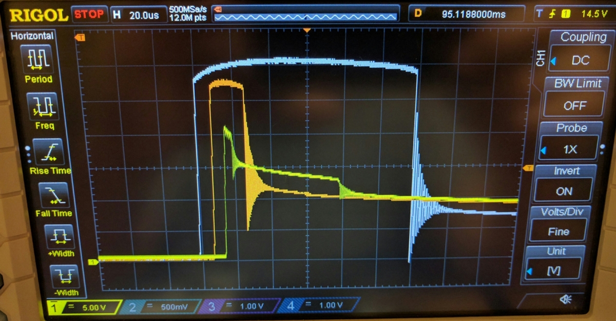
One way I really found out that the flyback is doing most of the work. I tried the TVS diode alone, and it immediatly blew the leg of the TVS diode on the first pulse. It's fine with the flyback there.

TEST SETUP

 )
)keen to see the results Doc, those tungsten tips are a work of art!Doctorbass said:I LOVE COPPER ! 8)
Here is the update on my build: (as well you will notice that the JP spotwelder is not there yet.. i need to replace all fets! :lol: i blown their gate when shorted them to too much copper :lol: it will be installed on the left of teh first picture you see on the top NEG bus bar from the caps.
The big copper bar you see is one of the two output lead of the system. These will be MASSIVE for maximum current!
-1.25" x 0.25" thick pure copper bus rail for high current connections from teh caps modules to the output tabs of the welder
-high quality industrial ultraflexible TRUE pure copper 4 gauge cable
-3/8" dia pure copper tip holder with fixing dual 8-32 set screw
-1/8" dia x 1" tungsten tip for copper spotweldfing
The measured total resistance of the system including the contact resistance on a 6 mil x 10mm wide copper sheet at distance of 5mm and capacitor ESR is only 2.0 miliohms.
And!...Total measured caps ESR is 0.12 miliohms. Enough for a 100 000Amps short at 12vbut that copper would vaposize in fract of a second before reaching that as well!
Total energy stored is 0.5Wh at max 35V ( close to 2kJ)
The highest resistance of the system will be between the two tips! :wink:
Doc
VirgilBudBrigman said:Finished spot-welding 240 cells (20S12P from 5 separate 4S12P packs, LG HG2 cells, 3000mAh/ea, 20A continuous each, total of 2.6kwh). Used 0.2mm x 8mm pure nickel, carefully laid out to achieve approximately 160-170A ampacity.
JP Welder has not been perfect, but I got through it! I blew a trace and a mosfet, but I put that down to the several feet of 1GA welding wire I originally used to extend from the car to the table. Later replaced all the MOSFETS with same type but automotive grade (like another $1-2 total, why not!?). Also implemented the diode mod (VS100BGQ045) that Okashira recommended. Of course, I also stopped using the long wires (less resistance) and implemented other mods, like the cooling fan and 12GA romex wire from the bus-bar to the MOSFETS. The whole thing runs VERY cool now, used to get almost burning hot! (Only the tips of the electrodes get warm when doing rapid fire welds)
The biggest issue I had (and a scary one) was several dozen times I had blowouts (craters), which are quite scary! My material is pure nickel and I experimented with differing pressure, timings, angle, cleaning the electrodes constantly, etc. I'm thinking the copper electrode material of these is not ideal...there must be something better! Furthermore, the wires themselves are not flexible at all...so I'm glad to see others looking to rectify these issues.
Another issue was sticking, and some of the copper getting left in the weld. This happened for up to half of all the welds. I tried the press and rotate technique others spoke of...which helps some. The sticking seems to contribute to the breakdown of the electrode, and needing to un-screw, put in the drill and spin it smooth and round/pointy again. I also lowered the settings down until pulling hard would "just" not break free of the cell.
I used a single brand-new Rural King battery (same as Exide Edge for a little more than 1/2 the cost, my wife's car battery had just died so the timing was perfect! http://www.ruralking.com/battery-auto-agm-rk-agm24f.html) and it worked VERY well. Before the mods I was up to 2/3 or so on the dial. After the mods, I was down to under 1/3 on the dial. Don't assume that you will need two batteries, for a good battery and 0.2mm nickel, you probably need only one!
SUMMARY: This spot-welding business is not for the faint of heart. Ironically, it's also not for the careless! Biggest improvements (post-mods) would be better electrode material and more flexible welding cables. (Or go with Headways if they dramatically improve the chemistry and you can fit them!
Geekineer said:Heres a question for the engineers in the group. How can I determine the root cause of my FET failures.
FETs blow either because of too much forward current during the weld time, or two much reverse current (avalanche) at pulse turn off. So from what I've read here you can:
Lower the forward current/shorten the weld time (lower FET heating) with 1. lower Rds on FETs, 2. lower voltage battery supply, 3. higher resistance (longer or smaller gauge power leads.)
Lower the avalanche current that the FETs see with 4. shorter non coiled weld leads (less inductance), 5. add a snubber diode. 6. add and RC snubber that lowers peak avalanche current but maybe not much lower energy.
Now then - how can I tell which of the above to do first when I want to keep my FETs from smoking. How can I tell if it was a forward or avalanche current failure .
Thanks for all feedback.
that1guy said:adriftatsea said:that1guy said:Decided to jump in the tab welder game.
Specs:
8x 0.11F (rated), 0.15F (measured), 15V ALEL caps => 120J
6x IRFP4004 MOSFETS, 40V, 1.35mΩ
6.35mm thick Al busbars
Any more pictures, this looks rad.
Did you mill the traces or use a photoresist? Any plans to sell kits/opensource? Voltage or discharge time adjustments?
Traces were milled with cnc machine.
Not pictured is a Teensy board that controls the show. I send it a request for via serial port for X energy on the caps. The Teensy charges or discharges caps to a voltage corresponding to E=1/2 * C * V^2. Pulse timing is also set via serial port. There's a weld pedal input pin, but that's also controllable via serial port.
I wouldn't mind open sourcing it once it's a bit more polished. I wonder how many people actually want to build a welder themselves with caps that have this same terminal spacing and threads.
I also made a spring loaded weld head. This part might be of more interest to the community.
markz said:Any news on the circuit schematic yet?


