
You are using an out of date browser. It may not display this or other websites correctly.
You should upgrade or use an alternative browser.
You should upgrade or use an alternative browser.
Landyachtz TopSpeed 90mm 10S4P DualRearDrive
- Thread starter whitepony
- Start date
whitepony
10 kW
- Joined
- Feb 19, 2015
- Messages
- 663
okp said:you got a pretty good amount of clearance between the motors & the deck !
hm, the motor mount is <0.5cm from the board surface at max lean angle. there is no room for more really!
whitepony
10 kW
- Joined
- Feb 19, 2015
- Messages
- 663
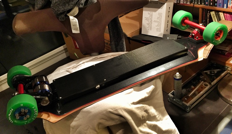
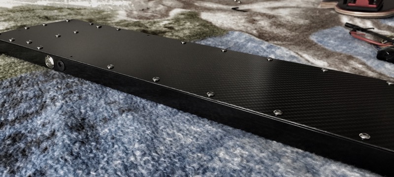
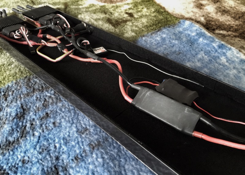
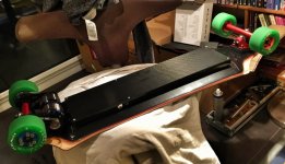
testmounted the new enclosure and it looks really cool, BUT: with the new snappy flex, the enclosure with the aluminum profiles actually puts the rubber mounts under a lot of stress because the enclosure is now very stiff while it just bent with the board before the aluminum profiles.
I accounted for rocker with some rubber washers, so the rubber mount is actually longer at front/rear and short in middle. what happens now when the board flexes: the front/rear rubber tube is stretched, the middle one is compressed. it worked well so far, but Im not sure for how long? :?
also it influences the way the board flexes which I really liked after its down to 7ply maple. maybe I will actually fall back to the even simpler first solution without the profiles over the whole length, but just with some partial profiles to get charge port and power button in.
Squad
100 W
- Joined
- Jun 28, 2015
- Messages
- 148
Looks rad! I love the deck shape You used, it screams "I'm super fast", but the flex is the last thing I would like to have in this set up. Maybe it makes the board more comfy but as You noticed it's kinda problematic when You use long battery pack and one enclosure (instead of two, like in my busted boosted :lol: ) I would reinforce the deck with CF to make it stiff, like okp did with his vanguard, but that's just my 2 cents :wink:
whitepony
10 kW
- Joined
- Feb 19, 2015
- Messages
- 663
its still quite stiff, im weighting 85kg and jumping up and down with as much force I can put in. even without riding it yet it feels like the perfect response now. before it felt a little like riding a wooden plank, now it stores just the right amount of energy. in the end its about carving for me, not about going 50kph (which I dont expect to be a problem either). ")
just hope that 2 extending vs 1 compressing rubber mounts will not end up with the profile midpoint touching the board. didnt think id get that much of an effect by sanding one maple layer off. if it works im probably the happiest whitepony in the world, cause with the flex as it is, i can perfectly tune damping with stance. usually im riding with a fairly wide stance, but for rough terrain i move closer to the middle to allow the board to take the edge off. this behavior is now noticeably amplified and it wasnt pronounced enough before.
ill make it work, the enclosure will have to follow the riding experience, not the otherway round!
just hope that 2 extending vs 1 compressing rubber mounts will not end up with the profile midpoint touching the board. didnt think id get that much of an effect by sanding one maple layer off.
if it works im probably the happiest whitepony in the world, cause with the flex as it is, i can perfectly tune damping with stance. usually im riding with a fairly wide stance, but for rough terrain i move closer to the middle to allow the board to take the edge off. this behavior is now noticeably amplified and it wasnt pronounced enough before.ill make it work, the enclosure will have to follow the riding experience, not the otherway round!
whitepony
10 kW
- Joined
- Feb 19, 2015
- Messages
- 663
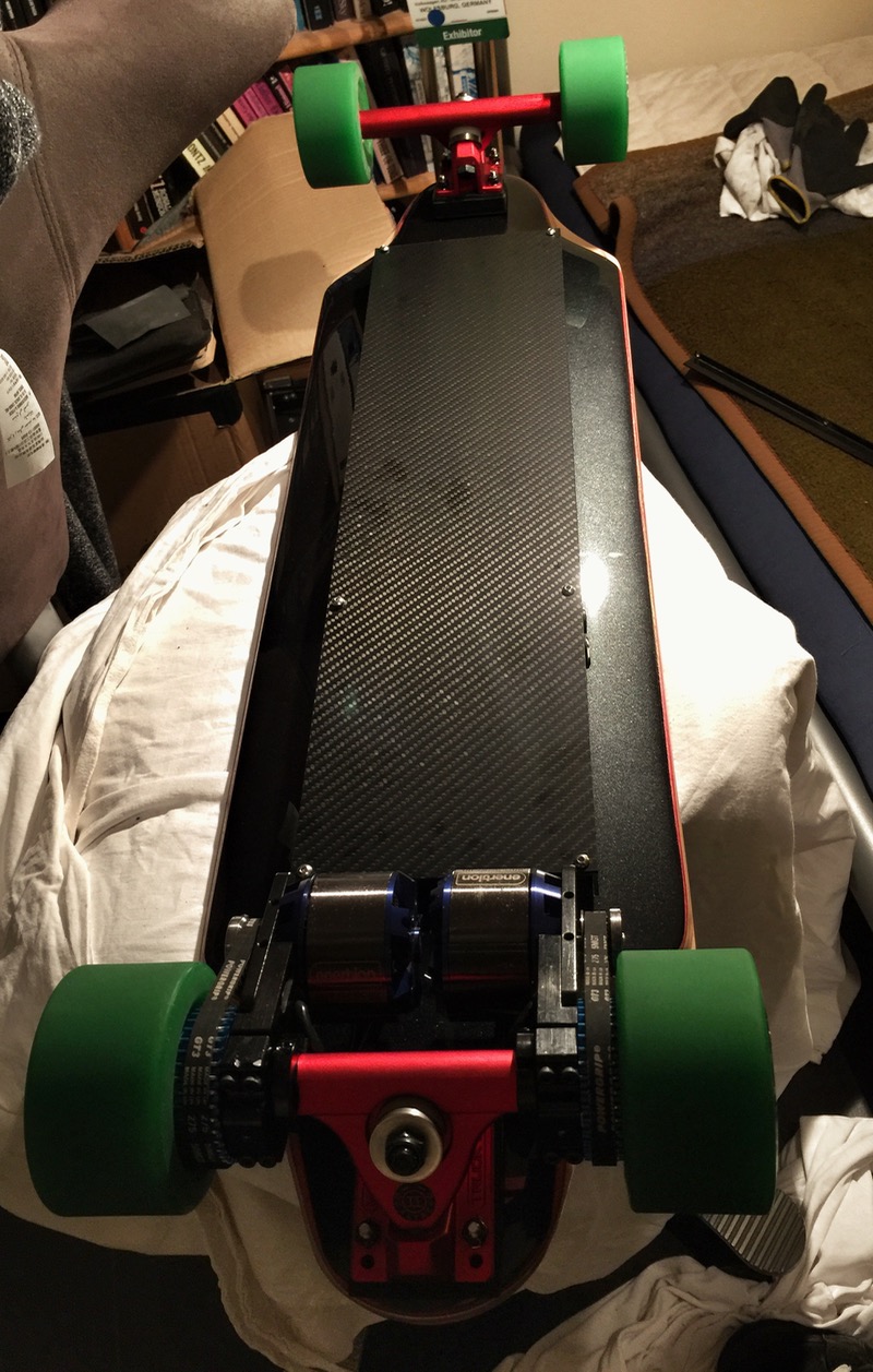
just returned from a 30km tour with the biggest grin in my face (despite all the leaves and twigs that were on the way  ). the flex is PERFECT! it really helps with the damping, especially when I take on the narrower stance like in the video, but feels as precise as it used to when I use the wider stance and carve hard. if i carve more in an easy going way I can use the narrower stance again and play with the energy in the flex, love it! 50kph is no problem ... as expected - in fact I couldnt tell the difference at max speed between 7 and 8ply maple. also, the aluminum profile is NOT touching the board surface at its midpoint, so it seems to be working out with the enclosure vs. boardflex. even took a few sidewalks and sidewalk->road transition to stress the board a little. seemed all fine!
one thing I still need to improve though: the carbon sheet can rattle against the aluminum profile on very rough ground or flagged floor. only got 3 screws per side and 2 of them mark start and endpoint of the battery. either I add a few tiny screws or maybe I just glue the profiles to the carbon?
one thing I still need to improve though: the carbon sheet can rattle against the aluminum profile on very rough ground or flagged floor. only got 3 screws per side and 2 of them mark start and endpoint of the battery. either I add a few tiny screws or maybe I just glue the profiles to the carbon?
It seems like it might be good if the box was split into two sections so the board could flex without over stressing the connections holding the box. If you landed real hard, seems like the middle of the board would bottom out on the box, possibly damaging something.
whitepony
10 kW
- Joined
- Feb 19, 2015
- Messages
- 663
mhm, im afraid of that too but today I pushed it without running into that issue (didnt even get close, else I had marks in the finish). only time will tell if the rubber mounts will keep up with the stress though. so far Ill just enjoy the sleek looks and well, if something breaks Ill fix it. can always split as a last resort.
whitepony
10 kW
- Joined
- Feb 19, 2015
- Messages
- 663
by the way, I was fiddling since a while now with wiiceiver vs GT2B in Badwolf enclosure: if you have access to a 3d printer or you are talented with epoxy like okps sleek design, I would recommend the GT2B out of the two. the control feels more natural and straightforward - might be index finger vs. thump though, I feel a lot more comfortable with index. the loss of the "cruise control" button is countered by the well weighted spring of the GT2B trigger mechanics. its easier to dial in the speed you want to drive and you feel directly at which speed your board will end up. also it feels that the gt2b trigger has a better resolution compared to the nunchuck which helps for throttle and brake control a lot.
I have to say though: if you arent into fiddling much, the wiiceiver probably wins. with the 2.0 update, it has an improved startup and braking performance (thanks to the new setup procedure I guess) and its the better looking and polished handheld product compared to a printed badwolf enclosure.
my conclusions in short would be:
if you dont want to fiddle much go for wiiceiver 2.0
if you dont mind fiddling and want better control, go for gt2b
whitepony
10 kW
- Joined
- Feb 19, 2015
- Messages
- 663
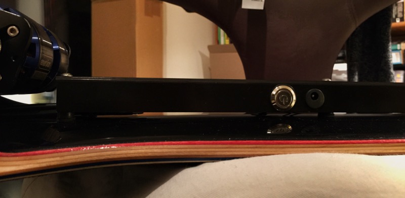
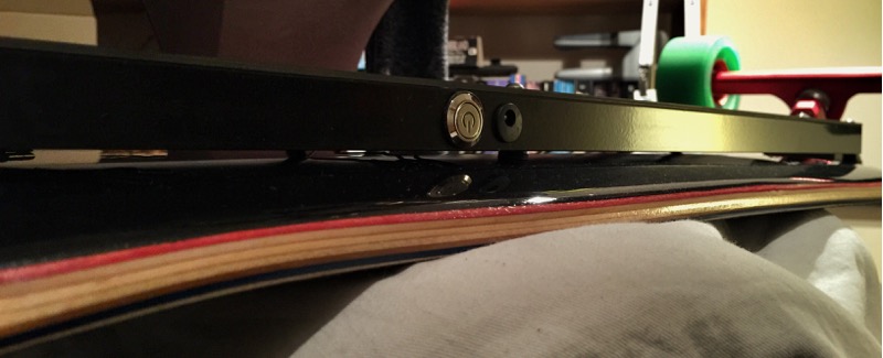
took this weekend to remove the rattling from the aluminum profile vs. carbon plate. there is a double adhesive tape between profile and carbon sheet now, combined with a row of additional screws. ontop of that, I extended the use of felt on the inside.
the "enclosure" lost some of the sleek beauty due to the million screws now, but dont think there was a another way to remove the rattling:
the "enclosure" lost some of the sleek beauty due to the million screws now, but dont think there was a another way to remove the rattling:
One other thought was if you moved the rubber mounts in a few inches from the ends of the box, you could accommodate more flex without breaking the mounts.
Looks really nice.
Looks really nice.
whitepony
10 kW
- Joined
- Feb 19, 2015
- Messages
- 663
fechter said:One other thought was if you moved the rubber mounts in a few inches from the ends of the box, you could accommodate more flex without breaking the mounts.
thats a very good idea.
I also think with the aluminum profiles, I could reduce the number of mounting points from 6 to 4. these 6 are still a remainder of my initial fiber plate enclosure without aluminum profiles.
I strongly doubt that Ill ever need to worry about these mounts though - earlier I tried to intentionally brake one of those rubber cylinders ... its NOT easy at all.
whitepony
10 kW
- Joined
- Feb 19, 2015
- Messages
- 663
today I nearly grilled my battery (not really sure). im still running without a BMS cause I thought I wouldnt really get into a critical battery voltage issue anyway with the typical 30km tours I make ... and the balancing so far has never been an issue - cells were on the same voltage up to 1/100th of a volt even after months of using (my evolve also runs without a BMS, I manually check regularly on the balancer cables though).
today I wanted to run into the 3.0V ESC cutoff to see where my touring limits actually are - was running the board like I always do - some high speed, some mid speed carving, few low speed segments due to wet leaves. at 32km my motors stuttered and I ran into the 3V cutoff the first time (as I thought). restarted the board and carefully cruised the last bit home, final 500m actually pushing. expected the battery voltage to be pretty healthy - like 32V maybe, hitting 30V due to voltage sag on hills/acceleration. boy, was I in for a suprise when I measured the voltage: 25V fuuuck
Im not really sure what happened, but 2 things are suprising here:
1.) the ESCs single cell voltage cutoff didnt work like I expected (I set it to 3.0V). thought it would be like my evolve - hitting threshold, power cuts out -> time to REALLY get home!
2.) my board has not really the best efficiency. 10S4P with 3000mAh = total energy of 432Wh. managed 33km with 25km/h average and a near deadly voltage cutoff (which basically means 100% discharge). substracted the last kilometer where I was basically pushing, so then its:
* 25.6km/h average
* 32km total
* runtime 75min
* max slope 9%
* total 120m up and down
* maxspeed 48km/h
* fastest average 2km segment: 35km/h
* esc settings: timing high, acceleration low
this means that my board was sucking about 345Watt for an average of 25.6km/h which seems hmmm, not very good really. this werent artificial 18km/h half throttle no carving test kilometers though, it was 100% normal whitepony use: heavy carving, different terrain, fairly decent slopes, quite a few full throttle segments.
wondering of its the discharge capacity of the battery, my supersoft 90mm 75A flywheels or just a semi-efficient drive train with the torqueboard ESCs -> rspecc motors -> 16/36T gearing. the board itself has very little drag, pushing that last kilometer was quite easy and downhill I often just let it roll without throttle.
superhappy with the board otherwise, that flex is just spot on, rattling gone, just a supersmooth carving machine up to max speed.
206monkey32
10 W
- Joined
- Mar 8, 2015
- Messages
- 78
Daaaaaamn ...will be interesting to see how that influences the packs life. Still sounds like you get quite a bit of mileage out of the one charge though.
whitepony
10 kW
- Joined
- Feb 19, 2015
- Messages
- 663
I think I have figured out why my battery was discharged to 25V despite the 3.0V/cell cutoff I set in the ESCs:
the torqueboard ESC only has the option to set the battery type LiPo/Nimh to determine the 3.6V vs. 1.2V base, but you can NOT enter the number of cells in series. so, what the ESC has to do to realize a cell voltage cut: take the (supposedly fully charged) battery, divide voltage by 4.2V, round up -> this is the number of cells in series, which then determine the voltage cutoff I set in the ESC -> in my example, I started with a full battery 41.4V -> ESCs figures out its 10S and sets the cutoff voltage to 30V.
midtour I switched off the board a little to rest and eat something, when I switched it on again lets assume a battery voltage 37V -> ESCs crunches numbers and realizes: aha, 9S battery, 3.0V/cell cutoff now 27V - sadly I in fact have a 10S battery. :|
but its getting worse from here: now I finally hit the threshold, the ESCs correctly goes into failsafe mode which it doesnt leave anymore on its own, so from that point on the board will not run electric anymore except for a superlowspeed emergency mode. usually the battery dips below a threshold under load from voltage sagging - with that battery knowledge in my head (assuming 31Vish -> voltage sagging below 30ish), I switched off the ESCs and turned them on again to restore normal mode.
but what I really did was: ESCs wake up -> oh, 27V, must be 7S battery -> 7x3.0V = 21V cutoff -> hurray, lets go!
this is a really bad vicious circle - incase you are running torqueboard ESCs and thought about relying on the cell voltage cutoff: you cant rely on it except for when you know exactly what you are doing. better to install a BMS or lipo saver.
torqueboards
1 MW
Sorry, we've had to figure this out the wrong way. Hope those batteries are recoverable. I'll see if I can modify that for the future and will let future customers know. I would assume to say a 3.4v would be a better cut off and a BMS/Lipo Saver.
My usable range for myself is usually 3.7 to 4.15 occasionally bringing it down to 3.4v but I also swap packs sooner than expected and/or check voltage sooner than expected. 20 mile ride is pretty long.
My usable range for myself is usually 3.7 to 4.15 occasionally bringing it down to 3.4v but I also swap packs sooner than expected and/or check voltage sooner than expected. 20 mile ride is pretty long.
whitepony
10 kW
- Joined
- Feb 19, 2015
- Messages
- 663
no worries, my batterie seemed ok, no warming up while loading, recharged it back up with the superslow evolve charger.
the change for the esc is really simple: change voltage per cell cutoff to a total battery cutoff, so people can enter for example "30". this rules out the "cells in series" evaluation and allows you to drop the nimh/lipo option. problem solved!
please let me know if you have a firmware upgrade that "fixes" this issue!
whitepony
10 kW
- Joined
- Feb 19, 2015
- Messages
- 663
one more thing: its a bit annoying that the escs dont recover from a voltage sag. the evolve cuts out, voltage recovers due to dropped load and after 5-6sec you can carefully reengage. that way you can still go quite a bit with very low throttle. given a fixed edc voltage cut, it would be very nice if the escs recover with recovered voltage!
whitepony said:waiting for parts is lame
Awesome Board Whitepony , Great build ! , love your battery pack also !
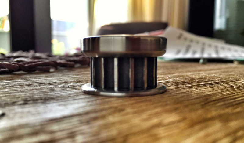
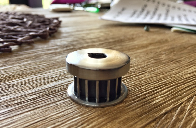
Where did you buy your motor gear, ..and do they make them in 15mm wide?
whitepony
10 kW
- Joined
- Feb 19, 2015
- Messages
- 663
the pulleys came from enertion with the r-spec motors in black finish. I used a lathe to turn them into these shiny gems.
dont think they are available in 15mm ... torqueboard has beautiful blue anodized 15mm versions, but you'd need the right motor for the width of these pulleys.
havent been super active, still waiting for my vesc order for my cantellated tesseract single motor lightweight board. the topspeed is holding up REALLY well, Im still in love with the board, the motors, flex and damping - even the last few days I was riding it cause the weather in germany is insane - preferring it to my evolve carbon AT even. 8)
whitepony said:depends on the motormount! with torqueboards v1 you can set it up at any angle/orientation!
Just wonder if it extend far enough to clear truck?
Similar threads
- Replies
- 2
- Views
- 917
- Replies
- 9
- Views
- 2,648