Arlo1 said:
Cool niles. So.... I tried with the 7kw colossus (80-100) and no luck sesnros are glued so then I went to the big colossus and got it to calibrate the coils but its still glitchy and I can not get termite to comunicate right when I first open it. And I push the reset button and it does nothing even though it should I have to cycle the main power to get termite to comunicate.
Code:
.5000	.5200	-.5400
.5000	.5200	-.5400
.5000	.5200	-.5400
.5000	.5200	-00	-.5400
.5000	000	..5200	00	.5200	-.5400
.5000	.5200	-.5400
.5000	.5200	-.5400
.5000	.5200	-.5400
I don't like this bit, something happens here in the communication. Maybe the there was a powerglitch ?
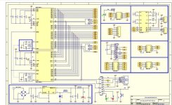
I looked at the schematic of the board you're using, I don't think the Xtal is the problem though I don't like
its connected to pin 14 (where there's supposed to be the drive_0 LED).
Looking at the schematic, there's a ferrite between the 1000uF cap and the main processor. This ferrite
a little bit isolated the supply after it, meaning the chip does not 'see' the 1000uF (to a small extent).
Comined with the glitch in the communication, I would solder at least 4 caps around the main processor,
preferably 47 uF or something like that (more of 10 uF or less of 100 uF should also be good).
I've seen really weird stuff hapenning when there's not enough capacitance. I remember the first time
testing the PWM, I would only see groups of 3 PWM pulses on the scope. I thought I programmed something wrong,
something which turned the PWM on and off. When I zoomed out though I saw the groups were 50 msec or
so apart and I realised the chip was resetting itself after 3 PWM pulses because the supply dropped (caused
by the sudden PWM activity). I added 200 uF worth of caps and this took care of the issue...
I wonder whether the problem lies with the MAX3232 interface chip, it has a lowest max rating of 120 kbaud, close
to the 115.2 kbaud I'm using. I also wonder whether it needs some toggling on the lines to get the boodstrap
supply going, I don't know never used these chips myself. If you got some bipolar transistors lying around i would
disconnect the MAX3232 and connect directly to RF4 and 5. The resetting difficulties you have are definitely not
normal.
It's a pity you did not plot the raw back-emf data (output the data arrays immediately after the back-emf sampling),
only the reconstructed version.... The reconstructed looks good though, not really sinewaves but good 120 degree
spacing. Same goes for the halls, looks good.

I would calculate the parameters you mentioned in your post with an LR_delay of 0.5 msec, the 0.089 msec (8u/0.09) from the
L and R values you post seems scarely low

.
The new chips go in the mail this afternoon, you're getting the updated version 1.01 . This version has as extra features
the pulsing of the low side FET's during drive_0 (see new manual which I will post later this week in the very first post
of this thread). Also it has the possibility to store the calibration data of the current sensors by pressing the setup
button during motor use (also see updated manual)

.jpg")
.jpg")

.jpg")


