Lebowski's motor controller IC, schematic & setup, new v2.A1

Wow Lebowski,

I am very impressed. You think you can ride all the way to Basel and show me? :mrgreen:
Alternatively, make sure to make some nice movies. I am sure it will be great to see your face the first time you can ride that controller!!
 
got my controller working again!

i have no idea what is wrong with the first pcb, but i ditched it and made a new one.
the new pcb worked on the first try, so i am happy. i hope i can finish the controller today,
and do some testing tomorrow (if the weather permits, its a bit rainy here the last few days)
 
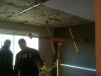
Sweet guys. I will be back on mine as soon as this is done. I put up my last big coat of mud last night. Im bagged I spend the last 2 days sanding and mudding. And the 3 days before that putting up genie clips furring channel insulation and drywal. Soon I will be back to my electric life!
 

Attachments

  • 006_renamed_32005.jpg
    006_renamed_32005.jpg
    41.7 KB · Views: 3,592
Amazing job you have done Lebowski!

I would very much like to contribute to the work with integrating your code/chip in ebike controllers. I have been building ebikes for a while and have pretty good theoretical and practical skills with electronics and electric propulsion. My daily job is as a SW developer at Volvo Cars and doing the functionality for the EV node in the Volvo C30 electric. http://green.autoblog.com/2011/04/05/first-drive-volvo-c30-electric-lovely-except-sky-high-price/

I have both rc and hub-motors of different types and some sensored and sensorless Lyen controllers that I can laborate with. Right now I'm building DH bikes with HS3525 and HS3540.
So if you're interested in one more test pilot I would would happily join :!:

My first EV build: http://endless-sphere.com/forums/viewtopic.php?f=28&t=19592&hilit=civil+disobedience


/Goran Jonasson
 
hi,

did some testing this weekend, but didnt get very far.

first i had my limits at 50a phase and 30a battery current. and it was kinda lame to ride totally no acceleration.
then i upped the current limits to 75a phase and 50a battery current. (i forgot to upp the fault current, still at 5a for option f and g) and it was cutting out everytime i gave it too much throttle. so i rode back home. 10 meters before i was there, the controller shut down again to drive 0. only this time it would not go to drive 1 again. so i brought the controller inside and scoped all the signal lines to the controller. one of the phase voltage sense lines was at 0.2v.. so what could this be? when i unplug my powerstage from the controller board the lines are at 2.5v again. i am thinking it is either my bottom c phase fet, or the fet driver on phase c. i hope it is the driver.. because i have one of those spare.. not any of the same fets:p (i do have some better fets, but then i need to replace all of them)

any ideas how i could check what the problem is? maybe the test signals without a battery connected? and see what the output looks like?

Niels
 
as it turns out, the driver is shot, and the fet is fine.

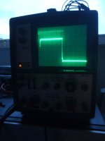
this is the output of the high side phase b driver (fine)
P4210028 (1).JPG

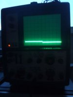
this is the output of the high side phase c driver
P4210032 (1).JPG

only the high side is not working, the low side is working fine.
 
For those of you waiting on the edge of your seat. I have about 3 hours of working on this since I got my chips from lebowski. I have bit to many things on the go. This is my own personal top priority but the girlfriend and the drag race hi and work and business come first. So soon but this is to everyone out there. DONT THINK POURLY OF THIS BECAUSE NO ONE HAS IT WORKING YET WE ARE JUST BUISY PEOPLE! I am sure this is going to be amazing!
 
Arlo1 said:
For those of you waiting on the edge of your seat. I have about 3 hours of working on this since I got my chips from lebowski. I have bit to many things on the go. This is my own personal top priority but the girlfriend and the drag race hi and work and business come first. So soon but this is to everyone out there. DONT THINK POURLY OF THIS BECAUSE NO ONE HAS IT WORKING YET WE ARE JUST BUISY PEOPLE! I am sure this is going to be amazing!
I'm certainly on the edge of my seat & have fallen off a few times too. :lol: :twisted:

I'm sooo pissed I don't have the electronics skills to do what you guys are doing, but I hope one of you can come-up with a kit or something that someone like me could assemble too. :idea: :D

It IS really frustrating just having to sit back and watch what I think is the greatest controller development project EVER on ES. We're fracking damn lucky to have you guys doing this. It's the best controller porn I've known. :p :shock: I can feeel it running smooth and silent... running deep into our wet-dreams of controller bliss. :twisted: :lol: :D

P.S. Hurry-up already, anyway! :twisted: :D
 
I got the chip and want to play with it so bad. Six months ago I had nothing but time, now there aren't enough hours in the day :( I hope to catch up on some of my own projects soon so i can start on this. If someone has a PCB designed it would be super fast even for me to start playing around. Maybe I can find some free time soon to get some designed and made. Gonna need something awesome like this for my mega powerstage.
 
At the moment I'm finishing my bike build (maybe this coming 4-day weekend :D ), after that
I want to make a 16x10 cm PCB containing a full 6 FET (hopefully TO247) controller
(including 100V or 150V to 18V/5V supply, controller IC, proper gate drivers and output stage).
For a 1 motor bicycle you then only need to connect analog throttle, the battery, the
3 motor wires and optionally the 5 hall sensor wires.
I think a PCB will make it very easy for everyone to build a controller. Just order the parts
from digikey (I will try to make a parts list), solder everything to the PCB, setup the controller
IC with your laptop and your vector based, sinewave out with automatic timing compensation
controller is done !
If the 6 FET proves itself I'll do a 12 FET or more version if there's a demand for it.
 
Lebowski said:
At the moment I'm finishing my bike build (maybe this coming 4-day weekend :D ), after that
I want to make a 16x10 cm PCB containing a full 6 FET (hopefully TO247) controller
(including 100V or 150V to 18V/5V supply, controller IC, proper gate drivers and output stage).
For a 1 motor bicycle you then only need to connect analog throttle, the battery, the
3 motor wires and optionally the 5 hall sensor wires.
I think a PCB will make it very easy for everyone to build a controller. Just order the parts
from digikey (I will try to make a parts list), solder everything to the PCB, setup the controller
IC with your laptop and your vector based, sinewave out with automatic timing compensation
controller is done !
If the 6 FET proves itself I'll do a 12 FET or more version if there's a demand for it.
I'm very excited to try this setup once you've got it ready. Hopefully will be buying many of these over time. Thanks for taking this to the next level of offering an order & parts kit. 8) :D
 
Before I'm putting my controller on my bicycle I wanted to play around
a little at try to spin a 10 kW Enertrac scooter hubmotor (which spkpn
gave to me, thanks dude !). It was kind of boring as it worked right
out of the box and I didn't need to change any settings w.r.t. my own
motor. in the video the e-rpm is limited to 1000 for safety... Or, you know, I'm
scared to think what would happen if this 30 kg (65 pounds) piece of metal
is spinning at high rpm and breaks lose of it's two tiny 6mm mounting bolts...

[youtube]HFyob3kkR70[/youtube]
 
Ok guys.... Where do I go from here.... I guess I will try a simple board build up with just the basics and get it working with a reset button properly?
I think my IOgear usb-serial adapter is giving me issues when I went to program my car two weeks ago it was a PITA and I had to remove the driver and re-install it.
SO whats a good serial adapter? Damb if I start from scratch I will need a max 232 which meens I need to put in another order....

Tonight I started with some new dspic chips and a dummy program lebowski give me to get a working setup before I fry anymore of his chips. I found the dspic was getting warm to the touch without doing anything I was just trying to get thought the setup menu. I also found even though the reset button puts the mclr pin to 0v it doesnt always wake up the menu so I think the serial adapter is to blame. Also leblowski shows a 2200 ohm resistor between the 5v and mclr which I dont have maybe I should?
 
I use a RS232 cable like this :
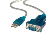
rs232.jpg

I tried 2 different brands of cable and a laptop which has the 9 pin RS232 build in, all worked
without any problems. Note that I use the 2 transistor interface as shown in the schematic, not
a MAX232 chip.

I never noticed the 30F getting warm to the touch ? try to measure the current from the 5V supply, it
should be a bit less than 200 mA... The reset button should work immediately and not 'sometimes'.

Arlo, try taking baby steps. Solder or breadboard from the beginning and after every step check supply
current and functionality (use a socket if you want to solder so you can swap chips and re-program using
the board you have already). First only solder all supplies and the mclr & setup pins (use switches or
jumpers for these last 2). Put chip in setup and measure supply current (less than 200 mA). If you have
a RS232 cable like mine, add the 2 transistors for the RS232. At this point (so without anything else
connected but supplies and RS232) you can already go into the menus and change all settings.
When this works, add hall sensor input lines and try hall calibration. After this, add the bit with
the 6 diodes and all resistors (2200 ohms, Ra, Rb). Now you should be able to measure backemf (main menu b).
Ask and plot all graph outputs to make sure all is OK. Every time you add some circuitry, measure
supply current to make sure it's not over 200 mA. When all is OK, connect FET drivers and FET's. Setup
the PWM and make sure it works like it should using the 'test PWM' options. Again check supply
currents. Take baby steps, that's how I did it.

The dummy program you got can spin a motor but use only at very low RPM ! It will only do a very bad sensored....
 
Lebowski,

How do you plan to drive that double wide Enertrac motor? That's the controller I want to build with your IC. :mrgreen:

Maybe I should start with a 6 fet, since the 6fet Kelly on my daughter's scooter, drives the motor quite noisily. Is it at a stage where relative beginners, but quick learners can give it a go? What's the minimum equipment required more than a good soldering iron and cheap multimeter? Soldering skill level required?

John
 
I've no plans yet for the Enertrac motor, the hub part has been removed to there's no easy installing.
I had a good look at it and it should be quite easy to attach a sprocket to it. Maybe I could use it
to install in my 1979 FXS and run a chain to a dry clutch but that would be sacrilege. Plus it would cost
a ton in batteries.

The next step for my controller is to make a PCB containing everything, I think once that's done it's
at a stage where a soldering iron and multimeter should be enough :D . At that point it's just a matter
of ordering a list of parts from Digikey, solder everything in the right place and set it up with a PC.

No clue though how long designing the PCB will take, never done that before (I've drawn 40nm IC layouts
though but it's not the same :D ). I guess learning the PCB tool will be the hard part.
 
What transistors would you sugest? I have 2n3904, 2n3906, 2n5061, and n43al lm293 iaz-5 (think its called a lm 293) in stock Would any of those 4 work?
 
Arlo1 said:
What transistors would you sugest? I have 2n3904, 2n3906, 2n5061, and n43al lm293 iaz-5 (think its called a lm 293) in stock Would any of those 4 work?

Use the 2n3904 . The others are the wrong type (pnp instead of npn), the 2n5061 is a thryristor and the last one I can't find...
 
Ok thanks man i will see what i can do.
 
Lebowski said:
The next step for my controller is to make a PCB containing everything, I think once that's done it's
at a stage where a soldering iron and multimeter should be enough :D . At that point it's just a matter
of ordering a list of parts from Digikey, solder everything in the right place and set it up with a PC.

No clue though how long designing the PCB will take, never done that before (I've drawn 40nm IC layouts
though but it's not the same :D ). I guess learning the PCB tool will be the hard part.

No worries. I've developed the patience of Job regarding a great high power sinus controller for hard to drive motors.

:idea: If I can get a battery deal done, then maybe we can barter....a big stack of great batteries to your door for a pair of high power controllers, one for use and one for backup.

John
 
I all of a sudden got very motivated to get the controller PCB done, cause in
my mind I'm already working on the next holy grail of controller design for which
I need a 2nd complete controller.

The plan is to add high torque startup or even high torque at standstill, SENSORLESS.

I did some measurement on the ME 602 scooter motor and found the winding
impedances change by + or - 15 % based on the rotor position, power needs
to be supplied to the lowest inductance (of the 3) to make the motor move.

I got some special stuff in mind for measuring impedances on the fly using
radio style signal processing. One thing I want though is to change only the
software, not the hardware. It should be possible, so lots of interesting stuff
to look forward to if only I had this bl00dy PCB done. And I haven't even
started on it yet :?

Can't promise it's going to work but it'll definately be an interesting ride :p
 
Back
Top