LVC for my 3S battery failed. Cells fell to 2.4V. What happened?

Delta

1 µW
Joined
Feb 21, 2021
Messages
2
Hello friends! First time posting in these forums.

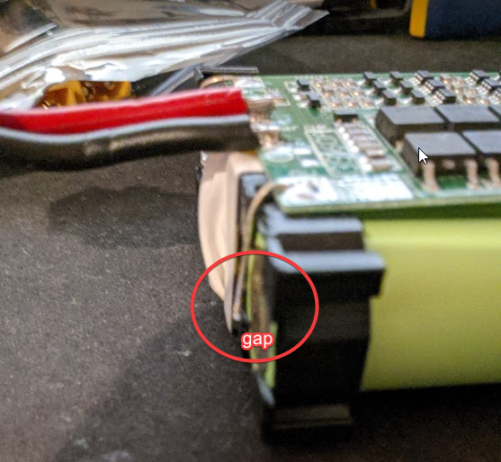
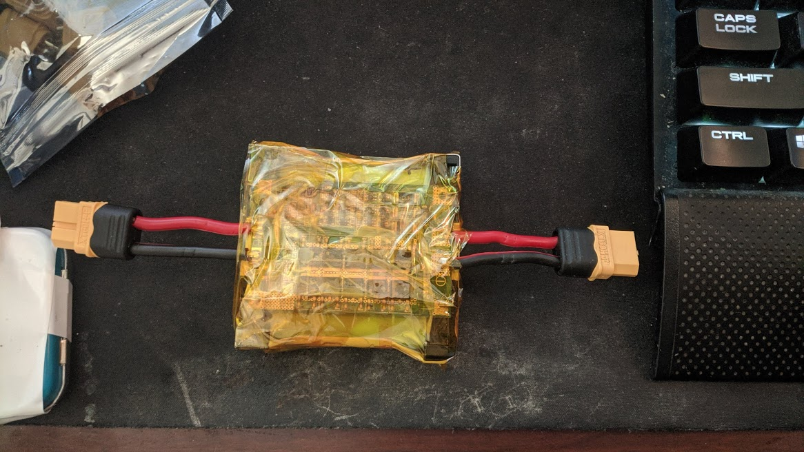
I've been working on a project which I have been powering with a 3S li-ion battery that I made with some 18650 batteries.
2oOybT6.png
Left is Charge, Right is Discharge.

It's been powering my project for about a month and I got suspicious about how long the battery lasted so I plugged it into my ToolkitRC smartcharger today and found that it was at 7.26V (2.42V per cell!).

I set the smart charger to charge the battery through the BMS's charge port and I see it ramp up the voltage to 12.4V 0A in which the charger tells promptly me it is done charging. I've also tried plugging it in to my ISDT charger which gives me a "abnormal battery connection" before I start charging it.

What exactly did I do wrong and why did my low voltage cutoff fail? A good portion of my project relies on LVC to work.

BMS from Aliexpress: 3S 60A Balanced Edition https://www.aliexpress.com/item/4001279276213.html?spm=a2g0s.9042311.0.0.32194c4dq2jFJu
Vendor's Spec Sheet: https://i.imgur.com/y40nz5B.png
 
The specsheet allows for lvc to be at 2,4 v so the bms is as far as I can see within spec..
 
Delta said:
I set the smart charger to charge the battery through the BMS's charge port and I see it ramp up the voltage to 12.4V 0A in which the charger tells promptly me it is done charging. I've also tried plugging it in to my ISDT charger which gives me a "abnormal battery connection" before I start charging it.
Most likely the BMS has shut off the charge port (and probably the discharge port) to prevent charging or discharging such overdischarged cells. Thsi will leave a "ghost" voltage that's not as high as the real voltage, from leakage thru them...until a load is put on the connector, and then it drops to basically nothing, if you want to test for this.

I'd also recommend testing the actual cell voltages, and not relying on dividing the voltage present at the outputs by three to find out what they are.


If the discharge port is not shut off, then the BMS probably has failed output FETs, which typically fail shorted (stuck on). They can fail from overheating, for instance, if the heat from the FETs in operation is high enough and can't escape. Or they can just be crappy FETs and died from internal faults. Or from ESD damage during handling, either before assembly onto the PCB or at any point afterward.


As for why it failed...could be the above, or if the FETs are good it could be the BMS is not able to turn them on or off correctly (gate drive), or the signal to the gate doesnt' work. Could also be the sense wire from any of the cells isn't working (broken wire, bad solder joint, etc).

If the BMS is based on an MCU, rather than a "dumb" BMS, the MCU could have crashed and no longer be checking the cell voltages or operating the FETs. Some of them have a reset button or jumper, and some of them have to be disconnected from the cells for a short period to reset them.


Could just be crappy firmware in the BMS that doesn't do what it's supposed to all the time, or that is set to the wrong LVC, etc.

Could be the cells themselves simply failed and self-discharged, or could be the LVC is so low and the cells not matched to that so that they got discharged down far enough that even the tiny drain of the BMS being powered by them is enough to drag them way down past empty.


Another problem could be the load. If you're using a 60A BMS...is that the actual level of current draw you're putting the pack thru? If so, that's a very high draw for what seems from the pic to be a 1p or at most a 2p pack. I don't know of any 18560 cells that can handle 60A.


FWIW, 2.4v is veyr very very very low, very very empty. I would not typically run cells down that low, 2.8v is already almsot completley empty for most of those cells. I'd actually stay at 3.0v or higher, even though this means a bit of capacity is left on the table, it means the cells will live longer.
 
amberwolf said:
Could also be the sense wire from any of the cells isn't working (broken wire, bad solder joint, etc)

First of all, thank you for your amazing answer! It provide so much insight into debugging what is going on with my battery. I decided to take off the kapton tape to expose the cells so I could measure them. Guess what I found?
B39WACa.png


Turns out my first cell was disconnected. I soldered it back on and my battery showed the proper 11.7V that it should have been. The individual cell was 3.89V. I guess it the solderjoint broke at some point (or it was broken all along and my project has been running on 7-8V this whole time.

:bigthumb: :bigthumb: :bigthumb:
 
Back
Top