MacGyver throttle fix?

mcintyretj

100 W
Joined
Mar 30, 2012
Messages
140
Location
Seal Beach, California USA
Hi all, I have had several throttle failures over the last few months. One of these was failed about 20 miles from home but was not an issue because it was on full/wide open throttle and I just worked the red button home. The other time was also 20 miles from home but I could not get any power so I had to peddle home 20 miles in the dark.

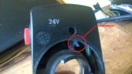
The throttle that failed on full power looks like one of the magnet came loose. You can see that both magnets are connected. I think that I can just super glue this back into place and have the throttle working again. My question is: does this magnet need to be aligned by polarity, or can I just glue it in any direction?

Here are some pictures:
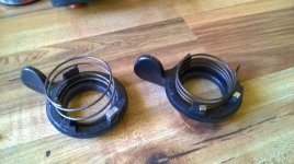
thumb parts looks like a magnet is missing.jpg

You can see that one magnet is missing/out of place on the right.


Here are the throttles:


View attachment 1

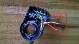
And a close up of the one that had the red wire disconnected from the sensor:
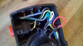
throttle with detached red wire.jpg

My question: Is there a quick fix that can be done out on a ride? I was able to pop this open and could see the problem but decided just to start peddling. Could two wires be spliced together and then use the red button to turn on/off the motor?

Thanks for any help
 
Bummer about your throttle, but it's neat to see what the guts of those throttles look like.

There was a post a few months back about someone fixing their throttle 'in the field' by just touching the wires together. If you have a CA, turning down the amps would be recommended before trying this. Most throttles are just ground, 5v, and the signal wire that's somewhere in between based on throttle angle. But the ones like you have with the built in LEDs usually carry battery voltage to power the LEDs - so randomly connecting wires might be a bad idea.

But as a guess, it looks like connecting 'red' and 'white' (or maybe 'red' + 'blue') together would complete the circuit at full voltage/throttle.
 
On a modestly powered ebike and the throttle failed far from home, after first trying to MacGyver the throttle itself to get it working, I'd try a direct connection of the 5V supply to the throttle sense with the wheel off the ground. If that works then I'd use my ebrake as the pulsing WOT throttle control...ie let off the ebrake to go. The new controllers I'm testing are programmable by smart phone, so it would be especially easy, because I could dial back current and change the throttle response for a comfortable ride back.

In the meantime, stop buying the same crap throttles that fail with such frequency. Even though they're cheap, I've found most throttles to be surprisingly durable as long as I don't do something to pull on them in a manner that breaks the plastic. You might look into trying GWhy's cable throttle to 5V hall adapter, so you can use something sturdy to pull a cable going to his throttle box.

John
 
One magnet pulls the throttle signal down and the other pulls it up, so the orientation is very important. Without any magnets, you get 50% throttle.
 
Fyi...if you put both magnets in backwards it will make the motor run full blast at zero throttle and go to zero rpms at full throttle...found that out fixing an older e bike that needed a new throttle...guess they used to put the magnets the other way than modern throttles do...
 
I think the magnets need to be oriented so they are repelling each other. Use better glue.
Test carefully with the wheel up before riding.
 
fechter said:
I think the magnets need to be oriented so they are repelling each other. Use better glue.
Test carefully with the wheel up before riding.

Really?

I have not experimented with those throttle sensors, but that would make a strange field for a linear response.

I would guess attracting would create a nice field to sense, but depends on what type of sensor setup they are using.

In any case, try it before cementing, find the orientation that works.
 
One magnet faces north and the other south to give a continuously changing magnetic field throughout the arc of rotation.
 
Re the Hall sensor being the other way....could be...but it was sure a lot easier to find a throttle I could pop out and flip the magnets on!
 
Most of them I've dissected use a ratiometric linear hall sensor. Output is V/2 with zero magnetic field (about 2.5v). The output goes lower when the magnetic field increases in one direction and higher in the other direction. If the magnets are oriented so they repel, the magnetic field will be near zero half way between them.
 
Thanks for the info.

I was able to test/play with the detached magnet and yes, direction does matter. My new ebay $15 throttle arrived at about the same time so I decided to repair one on my broken throttles and just cut the connectors to the one with the broken sensor and scrap that one. These throttles are cheap but one failed at about 10k miles and more than 18 months of riding. the other only lasted 2 months but I was not treating them gently and would let it snap back from full which is probably why the sensor broke, and, also why the magnet cam loose. In the future, I will decelerate just as gently as I accelerate.

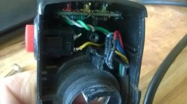
This is the 10k+ mile throttle with the fixed/super glued magnet. I had to glue a piece of plastic onto it to keep it from pushing/sliding away. This will be a back up for now.

View attachment 5

My new $15 (shipped) ebay throttle arrived but the connectors were not the same so I cut these off and replaced them with the connectors from the broken (sensor) one.

View attachment 4


The test I really wanted to do but ran out of time (because I needed to get out for a ride) was to twist the 3 sensor wires together (red=+5v, white?, blue= gnd) and see if that worked to get power.
Here is a schematic of the yescomusa.com throttle.

throttle schematic.jpg

Would connecting the red, white and blue (sometimes black) wires work? Has anyone done this? I can easily pop open the unit, even while it is on the handle bars, and and connect these with a simple multi-tool.

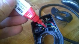
Also, This afternoon, I pulled of the throttle that has been on my 500w bike for 2.5 years. Lately, the response has been inconsistent with some dead spots. I knew the sensor had come loose earlier but just shoved it back in and it seemed to work OK but not at 100%. I found the sensor had slipped out of place and twisted some. So I super glued that as well and will give it a try tomorrow. Here are some photos:

throttle that came with my first 500w 48v kit 1.jpg

sensor loose out of place and twisted.jpg

adding glue to hold the sensor in place.jpg

I own several cheap Chinese conversion kits and, I admit, that nothing about these kits looks like quality, however, I have had amazing results from just about every component (knock on wood). I read a lot here and realize that not everyone has been as lucky. Thanks again for all the information and Happy new year!
 
If you short +5 and ground it may damage the controller.

If you connect the throttle wire to ground it will be like throttle off.

If you connect the throttle wire to +5 it will either be full throttle or more likely trigger the broken throttle safety feature in the controller and cause it to reject the throttle signal, again equalling no throttle.
 
Did you test the polarity of the magnets?

Slamming the throttle off is most likely why it failed, but it should be designed to withstand that.
I think they just need thicker plastic around the stops and the magnets. Aluminum would work too.
Having some thin rubber bumpers things hit against might help as well.
 
Back
Top