Meanwell clone- AD488.3-400W power supply mods

fechter said:
I'll take a look. Can you read any number off the 16 pin chip?

What model is the supply?

The number of the 16 pin chip is: 15407YH TL494CN

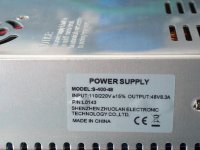
The supply model is 48V 7.5A 360W
Bought it here: http://www.ebay.com/itm/311001005100?_trksid=p2057872.m2749.l2649&var=610293600576&ssPageName=STRK%3AMEBIDX%3AIT

Is it possible to reduce the current with your method on this supply?
 
I don't have enough of the board in the pics to be sure, but R35 looks like the one to put a pot across to lower the current.

To be sure, I need to trace the circuit back to the shunt, which I don't see in the pics.
 
fechter said:
I don't have enough of the board in the pics to be sure, but R35 looks like the one to put a pot across to lower the current.

To be sure, I need to trace the circuit back to the shunt, which I don't see in the pics.

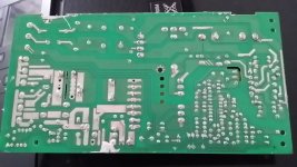
Are you able to trace the circuit back to the shunt on this picture?

View attachment 1
 
fechter said:
I don't have enough of the board in the pics to be sure, but R35 looks like the one to put a pot across to lower the current.

To be sure, I need to trace the circuit back to the shunt, which I don't see in the pics.

Here is a video of the circuit:
https://www.dropbox.com/s/ieesyv8h3xree0k/20160211_141817_001.mp4?dl=0

Are you able to trace the circuit back to the shunt on this video?
 
kje said:
fechter said:
I don't have enough of the board in the pics to be sure, but R35 looks like the one to put a pot across to lower the current.

To be sure, I need to trace the circuit back to the shunt, which I don't see in the pics.

Are you able to trace the circuit back to the shunt on this picture?

View attachment 2
Could you see anything on the video or picture? ☺

file.jpeg
 
Sorry for the delay, yes I can trace it back to the shunt now.

R35 is the one. I can't tell what the stock value of R35 is, but you could measure it with an ohmmeter or tell from the color bands. Anyway, reducing the value of R35 should lower the current limit. You could try placing a trimmer pot across it and see what happens.
 
fechter said:
Sorry for the delay, yes I can trace it back to the shunt now.

R35 is the one. I can't tell what the stock value of R35 is, but you could measure it with an ohmmeter or tell from the color bands. Anyway, reducing the value of R35 should lower the current limit. You could try placing a trimmer pot across it and see what happens.

for what its worth, R35 is the same name as the one for all of my modded meanwells. lol.
 
fechter said:
Sorry for the delay, yes I can trace it back to the shunt now.

R35 is the one. I can't tell what the stock value of R35 is, but you could measure it with an ohmmeter or tell from the color bands. Anyway, reducing the value of R35 should lower the current limit. You could try placing a trimmer pot across it and see what happens.

Thanks. I'll give it a try.
 
Fechter, If I lower it to 38v... do you think it could sustain the 8.3A continuously?
I have a friend with a Zero FX that is considering running 3 of these in series for 116v charging. That combined with the onboard 650w charger would max out a normal 120v/20a outlet.
Personally I am trying to persuade him to run some other options, but he seems to have his mind made up on cheap meanwell knockoffs.
So far I at least persuaded him to run 3 instead of trying to run 2 and upping the voltage.

My personal belief is that it will overheat, or the fan will cut out and it will overheat. Does it even detect if the fan is spinning or if the board is running hot?
 
8.3A labeled-rated is no indication of actual regulation.
Even Genuine MeanWells of 7.3A labeled-rated output ~10A (130% of rated for surge handling)

Any use should necessitate a metered and regulated throughput!
Regulating 1 of 3 in series is effective.
(Confirm PS are electrically isolated! No continuity between DC negative and AC Ground etc. Test series, 1st power up through 100w light bulb?)

Be Aware!
I purchased recommended 48V 400w PS but received different model.
Listed model has changed, from same link.
Waiting for response from seller before cracking open PS.
Seller on Chinese vacation till ?

400w 40V.jpg

Update:
Preliminary inspection (through slots) indicates that received model has same internals.
 
MrDude_1 said:
Fechter, If I lower it to 38v... do you think it could sustain the 8.3A continuously?

Not under all conditions. I think it will run hot. With enough air flow, it would take it.
With the stock fan, I think you might need to bump it down a little to keep the temp reasonable. Temperature is the limiting factor.
 
fechter said:
Sorry for the delay, yes I can trace it back to the shunt now.

R35 is the one. I can't tell what the stock value of R35 is, but you could measure it with an ohmmeter or tell from the color bands. Anyway, reducing the value of R35 should lower the current limit. You could try placing a trimmer pot across it and see what happens.

I placed a trimmer pot across the R35 and tried to charge my 48V battery but the pot doesnt do anything. It has to be said that the current was starting at about 5A and went downward. The voltage was just 51.6V at maximum so I need to get the voltage up. Is it because the low voltage the trimmer pot doesnt do anything?

Would placing a 10k resistor across R40 raise the voltage on my power supply as well?
 
If the voltage isn't high enough for the pack, the current won't be at the limit, so the limiter circuit won't do anything.

Let me check which resistor will take it up.
 
fechter said:
If the voltage isn't high enough for the pack, the current won't be at the limit, so the limiter circuit won't do anything.

Let me check which resistor will take it up.

Great. I'm looking forward to it. :)
 
fechter said:
Oops, the picture I have of the top side doesn't show the voltage adj pot.
Here is a video of the circuit:
https://www.dropbox.com/s/ieesyv8h3xree0k/20160211_141817_001.mp4?dl=0

And here is a picture:
https://www.dropbox.com/s/45zj8devjzcydvb/20160219_160959.jpg?dl=0

And a close up picture:
https://www.dropbox.com/s/1lgmppbfsho8jmo/20160219_161200.jpg?dl=0

Does this help?
 
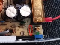
It's funny how they are all so similar but just slightly different. Anyway, it looks like if you put a resistor across the one in the pic below, it will raise the maximum voltage.
I can't make out the color bands, but based on experience, you could try 15k-20K across it and carefully dial it up and see what you get.

Some supplies have secondary limiting, so it might only go so far. Also note the voltage rating of the output caps and don't go past it.

Meanwell Top closeup.jpg
 
Received different labeled item from same link.
Internal pcb is labeled same, and appears identical.

Tests, so far:
OEM
Voltage range - 53.18V - 33.09V
R35 = 1k
R40 = 1.5K
Fan speed varies with voltage adjustment. Tested for thermal fan regulation via hairdryer = no change, will monitor during 10A+ charge.
(Fan speed change determined via LED light w\pwm low setting - wagon wheel effect)
Idles 8w (no load)

Preliminary guess for maximum usable range. (Will confirm next week.)
Replace R35 w/1K external pot 0A - 10A+ adjustable
Replace R40 w/2K external pot ~28V - 63V adjustable
Will add V-A meter ...

Running my 33.3V 43.2Ah battery down .
Will use to test oem Amp output @ 37.35V (anticipate 10A+ ?)

Will also test add resistor values for limiting amps and increase voltage ...
 
fechter said:
kje said:
Nice. Can I do this with a 10k trimmer pot?
Yes, if that's easier. A fixed resistor will just change the range of the stock voltage adjuster.

I soldered a 10k trimmer pot to R40 but when I powered the power supply I blowed one of the capacitors as you can see on the picture below.

https://www.dropbox.com/s/rq765ytyt17sjrv/20160222_200153.jpg?dl=0

https://www.dropbox.com/s/ib2tyxoomksoz8i/20160222_200016.jpg?dl=0
 
Make certain you don't adjust R40 above 63V ...
Or you will blow a cap.
 
It probably went over the 63v rating and blew. Luckily, if that one goes, there's a good chance everything else will be OK. Just replace the cap. Even with a higher voltage rated cap, I wouldn't go over 60v or so. The output diodes will be next.
It's possible your 10k trimmer was set to less than 10k and/or the main adjuster wasn't all the way down to start.

You can use an ohmmeter to make sure the trimmer is at the maximum value before powering on. Make sure the main adjustment is all the way down to start. After powering on, you can tweak things gradually. Sorry if I didn't make this clear the first time. Ideally, you want the trimmer set so the main adjuster can go to maximum and be just under 63v.
 
Back
Top