The USP-350-24 is the big brother to the USP-225. Like the 225, it has an extruded U-channel frame and no fan.
Universal AC input / Full range
Built in active PFC circuit compliance to EN61000-3-2
Protections: Short circuit / Overload / Over voltage / Over temperature
Free air convection for 300W and 350W with 23.5CFM forced air
High power density 6.3w/in
ZVS technology to reduce power dissipation
Active AC surge current limiting
U-bracket low profile:38mm
3 years warranty
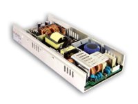
Like any other MeanWell, to use it as a battery charger generally requires a way to adjust the current limit lower in order to keep the power below the rating and avoid excessive heat. This can be done by placing a potentiometer across an existing resistor. Rather than trying to attach wires to a tiny chip resistor on the bottom of the board, there are traces on the top that go to the correct spots.
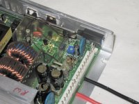
The general area is here:
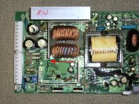
The board seems to have a conformal coating, so this must be scraped off in order to solder. I scraped off a little of the green solder mask to increase the area I can attach to.
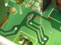
Next, tin the spot with solder:
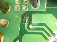
Next attach a small gauge wire long enough to reach where you want to locate the adjustment pot.
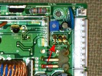
The second connection is right where the empty shunt hole is. The peroforated bus bar is also connected to this spot and would work as the second point.
View attachment 5
The resistor we are attaching to is R105. Here is a partial schematic of the voltage and current regulator. The stock value of R105 is 1.1K. Lowering this value will lower the current limit. By placing a 5k-10k pot across this, you can adjust the current from near zero to about 90% of the stock rating. I used a 15 turn trimmer pot from the junk box. After attaching the wires, I covered the whole thing with heat shrink tubing to prevent any accidental connections.
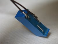
The pot was then attached to the frame with some double sided foam tape:
Voltage Regulator
The stock adjustment range was about 19.7V to 28.2V. If I want to use two of these in series for my 14s pack, I will need just a little more voltage. Ideally up to 30.0v in my case. The maximum voltage can be increased by adding some resistance from the negative output to the OVP test point. It won't take much to get another 1.8V, somewhere around 68K or alternately you could use a 100K trimmer pot to change the maximum voltage setting.
If a lower voltage is needed, a resistor can be placed between the OVP test point and positive output.
The OVP test point is here:
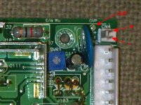
Unfortunately, the secondary OVP circuit kicks in before reaching 30.0V. The secondary circuit is a backup to the primary circuit. Secondary OVP is set by the values of ZD 101 + ZD 102. To nudge the secondary cutoff a little higher, we can lift one side of ZD 102 and place a diode in series with it. A 1N914 or almost any regular diode will add about 0.7V. Note the polarity of a regular diode will be opposite that of the zener (banded ends would go together). Alternately, you could replace ZD 102 with a slightly higher voltage one.
Below is a partial schematic of the voltage and current regulator parts. Knowing the resistor values, one can calculate the exact resistance needed for a given change.
Universal AC input / Full range
Built in active PFC circuit compliance to EN61000-3-2
Protections: Short circuit / Overload / Over voltage / Over temperature
Free air convection for 300W and 350W with 23.5CFM forced air
High power density 6.3w/in
ZVS technology to reduce power dissipation
Active AC surge current limiting
U-bracket low profile:38mm
3 years warranty

Like any other MeanWell, to use it as a battery charger generally requires a way to adjust the current limit lower in order to keep the power below the rating and avoid excessive heat. This can be done by placing a potentiometer across an existing resistor. Rather than trying to attach wires to a tiny chip resistor on the bottom of the board, there are traces on the top that go to the correct spots.
The general area is here:

The board seems to have a conformal coating, so this must be scraped off in order to solder. I scraped off a little of the green solder mask to increase the area I can attach to.

Next, tin the spot with solder:

Next attach a small gauge wire long enough to reach where you want to locate the adjustment pot.
The second connection is right where the empty shunt hole is. The peroforated bus bar is also connected to this spot and would work as the second point.
View attachment 5
The resistor we are attaching to is R105. Here is a partial schematic of the voltage and current regulator. The stock value of R105 is 1.1K. Lowering this value will lower the current limit. By placing a 5k-10k pot across this, you can adjust the current from near zero to about 90% of the stock rating. I used a 15 turn trimmer pot from the junk box. After attaching the wires, I covered the whole thing with heat shrink tubing to prevent any accidental connections.

The pot was then attached to the frame with some double sided foam tape:

Voltage Regulator
The stock adjustment range was about 19.7V to 28.2V. If I want to use two of these in series for my 14s pack, I will need just a little more voltage. Ideally up to 30.0v in my case. The maximum voltage can be increased by adding some resistance from the negative output to the OVP test point. It won't take much to get another 1.8V, somewhere around 68K or alternately you could use a 100K trimmer pot to change the maximum voltage setting.
If a lower voltage is needed, a resistor can be placed between the OVP test point and positive output.
The OVP test point is here:

Unfortunately, the secondary OVP circuit kicks in before reaching 30.0V. The secondary circuit is a backup to the primary circuit. Secondary OVP is set by the values of ZD 101 + ZD 102. To nudge the secondary cutoff a little higher, we can lift one side of ZD 102 and place a diode in series with it. A 1N914 or almost any regular diode will add about 0.7V. Note the polarity of a regular diode will be opposite that of the zener (banded ends would go together). Alternately, you could replace ZD 102 with a slightly higher voltage one.

Below is a partial schematic of the voltage and current regulator parts. Knowing the resistor values, one can calculate the exact resistance needed for a given change.

