Motor Hall Fault

Thoughts... not in any particular order.

bhagudunk said:
Current hall sensor installed is A3144 (linear type)

From your description of switching between 3.3vdc and 0vdc. (no stray linear voltages in between) And looking up the data sheet on this type hall sensor. It looks to me that it is a Unipolar type hall sensor. Which works well on some BLDC systems. Proven with use on your other controller.

With that in mind... Is your Chinese controller a sensored and non-sensored controller? I.E. will your motor work with the hall sensors unplugged?

Reference: https://www.digchip.com/datasheets/parts/datasheet/029/A3144-pdf.php


bhagudunk said:
...and I already bought 41F type (bipolar) from local online marketplace.
Is it OK with this type?

SS41F is a commonly used Bipolar hall sensor for Ebike motors.

Datasheet: https://www.mouser.com/catalog/specsheets/hwsc-s-a0001295895-1.pdf


bhagudunk said:
Note : current hall sensor works well with my old China 45 amps controller but reported faulty with my new Votol em100.

Does your new controller software AUTOMATICALLY configure your sensors to windings? Determining the angles and degrees?

If not have you set them up correctly?

bhagudunk said:
QS document stated above clearly indicate that QS Motor (which is the best match of Votol controller) using bipolar hall sensor that give 0V (off) and 5V (on) output.
Back to the ground, one thing I still don't know is whether I have to use 10K resistor soldered to +5V and the output leg of each hall sensor or not.
I guess the controller has this component attached internally.

Please take a longer and closer look at the testing thread...
https://electricbike.com/forum/foru...-motor-s-phase-wiring-hall-sensors-and-wiring
I try to explain how the hall reference signal from the controller is sunk to ground by the motor's hall sensor.
Now this signal can be 5vdc, or it can be the 3.3vdc that you are showing now.
These values would be the high water mark, with the activated hall sensor sinking the reference signal to ground for the 0vdc, or low water mark.

The resistors are only required when you are testing the motor's hall sensors when they are DISCONNECTED from the controller.
They are indeed internal to the controller.

I stand by my recommendations on how to test.

Sorry, I didn't start by reading this entire thread. Thought it was another one I'd posted too. Alot of this has been covered previously...
 
Drupa said:
I came across a document today from QS Motors which explain how to test their motors hall sensor & found out it wasnt the same way I measured!
I was connecting multimeter negative probe to black wire in hall connector & posstive probe to each one of the 3 halls (YGB),
The results were 0v or 3.29v

QS document state that the Red probe of multimeter should be connected to the red wire of the hall connector & the black probe
to each of the halls (YGB) & I should measure either 0v or 5v. When tested the new 2000w motor that way I got on all 3 sensors 5v or 1.9v !!!
Is that means that all my 3 sensos are bad???

That might be the root cause for the cutoff
Thanks
It's exactly the same test.

The only difference is the reference point (where "ground" is on the meter).

The difference between the supply voltage at the red wire and the lowest voltage reading of the two you get when using red lead on red wire and measure signal using black lead is the same voltage you get if you put the black lead on black wire and measure signal using the red lead.


The highest voltage you should see on the signal line, using black as reference ground, is the pullup voltage on the controller's hall signal lines. Unplug the motor from the controller, and check the voltage from black to signal line *on only the controller hall connector*. That is the pullup voltage.

Then reconnect the motor to the controller, and measure the voltages from black to signal line, and it should be the same for any hall that is not turned on. (on, for these halls, is grounded; off is floating so whatever voltage the controller puts on the signal line).


If the controller doesn't put 5v on the signal line, you'll never see 5v there.

Some controllers may put as low as 3.something volts on the pullups, which means you can have problems with electrical noise from the phase wires / motor coils, etc causing noise spikes in the hall signals and cause the controller to have so much trouble reading the signals that it can't correctly drive the motor, especially under higher loads (more current).

The higher the voltage on the pullups, the cleaner the signal. Some controllers use 12v (or more) on there for that reason. (they still usually use 5v to power the halls on the red wire).
 
TommyCat said:
With that in mind... Is your Chinese controller a sensored and non-sensored controller? I.E. will your motor work with the hall sensors unplugged?

It's only sensored controller
 
TommyCat said:
Does your new controller software AUTOMATICALLY configure your sensors to windings? Determining the angles and degrees?

As far as I know, Votol EM100 doesn't have automatic angle detection feature. But I'm sure that my motor has 120 degree angle.
 
TommyCat said:
https://electricbike.com/forum/forum/kits/golden-motor-magic-pie/110168-testing-bldc-motor-s-phase-wiring-hall-sensors-and-wiring[/url]...

Yes TommyCat, I have already read your thread few months ago. A very helpful thread.

While waiting new hall sensor to come, I checked both the Votol controller and the hub motor using BLDC Tester, I found something interesting :

I'm faking the controller hall wire with BLDC tester (connected hall wire and phase wire of controller to BLDC Tester). It works, and the controller looks fine.
Then I connect motor hall wire (using 3144 hall sensor) to BLDC Tester, rotating the wheel forward slowly. Tester shows that motor hall sensor is good too.
Then I test motor phase wire, BLDC tester shows all phase wire is normal.
Test all three phase wire using multitester, all wire shows about 50 ohm. No short of all phase wire to motor body.
But when I connect controller to motor, and turn the key on, both controller software and dashboard indicator show "motor hall fault" sign and controller stop working.

I also checked hall sensor power source (red & black of controller hall wire), it shows 5.46 V and stable.

Is anyone know whether Delta Windings on motor to be the cause of this strange situation?

Rgds.
 
TommyCat said:
Please take a longer and closer look at the testing thread...
https://electricbike.com/forum/foru...-motor-s-phase-wiring-hall-sensors-and-wiring
I try to explain how the hall reference signal from the controller is sunk to ground by the motor's hall sensor.
Now this signal can be 5vdc, or it can be the 3.3vdc that you are showing now.
These values would be the high water mark, with the activated hall sensor sinking the reference signal to ground for the 0vdc, or low water mark.

The resistors are only required when you are testing the motor's hall sensors when they are DISCONNECTED from the controller.
They are indeed internal to the controller.

I stand by my recommendations on how to test.

Yes TommyCat, I already read the thread few months ago. A very helpful thread.

While waiting new SS41F hall sensor to come, I do some test with BLDC tester & multitester :

Check the hall sensor power source from controller with multitester shows a stable 5.46V.
Check all 3 phase wire of motor shows the same resistance (about 50 ohm). No short between phase wire and motor body.

Testing the controller & hub motor with BLDC tester shows results below :

Connecting controller hall wire and phase connector to BLDC Controller, then run the controller. It shows normal and looks like there is no problem with the controller.

Connecting motor hall wire (using existing 3144 hall sensor) with BLDC Tester and rotate the wheel slowly forward, it shows that hall sensor is fine too

Connecting motor phase wire to BLDC tester and rotate the wheel, it shows normal too.

Then, I connect controller to hub motor completely, and turn the key on. Both bike dashboard and controller software show "motor hall fault" and controller locked, no wheel movement.

Is there possibility of motor Delta Windings to be the cause of this strange situation?
I mean, maybe Votol controller can not accept Delta winding motor, while my old controller run with no problem with Delta winding motor.

Rgds
 
Sorry for posting twice, I thought that the first post was not delivered due to internet problem :D
 
Hi bhagudunk,

The advanced work changes on the motor seemed like a possible link to an issue. But as you say, it works with the old controller. :roll: What could be different between the old and new controller?

What sticks in my mind is, that the controller instantly recognizes a hall sensor issue. Like it immediately sees from the sensor input readings that something is amiss.

As you know, the sensors toggle "on" or "off". But they also must toggle in a correct sequence, and numbers of hall sensors "on" or "off". In a 120 degree system, when rotated I believe that they toggle with...

2 "on"
1 "on" Ha
2 "on"
1 "on" Hb
2 "on"
1 "on" Hc

With the progression chasing itself around the circle. (thinking of a typical tester.)
Can you see this with your BLDC tester?
What tester is it?

With the system all connected and powered up, can you back probe on the controller side hall sensor connector, signal reference voltages, to see if more than two are "on"? Or all "off". Or perhaps a bad connection in that connector?
I.E. Move to one position, take all three signal readings, move to next change point and re-read... ECT. Anything interesting?

Just to add, and not that I think if would matter as far as the hall sensor fault. And with motor winding way above my knowledge level.
It just seems that 50 ohms for one winding phase is excessive...? All 3 are the same, right?


Regards,
T.C.
 
TommyCat said:
It just seems that 50 ohms for one winding phase is excessive...?
I'd say that's excessive, but they usually can't be accurately measured with typical multimeter. Even one like my DE-5000 LCR meter isn't easily able to accurately do so.

Phase windings typically read in dozens to perhaps hundreds of milliohms (thousandths of an ohm), because it's just coils of wire.

See this thread
https://endless-sphere.com/forums/viewtopic.php?t=105637
for some motor measurements with that meter (and at least one chart of values to be expected for one motor design).
 
Hi all,

After hall sensor SS41F arrived, I install it with 120 degree as per hub motor default, then connect it to controller, power key on, and rotate the wheel forward slowly. Hall sensor fault error sign appear again in the dashboard.

I thought that there must be something wrong with the controller that I can't manage. The only way is to try to change the motor hall sensor configuration to 60 degree.

To change from 120 to 60 degree is not a difficult thing. I just change the 2nd hall sensor (the center Hall sensor, phase B, usually green wire) to be faced down, facing the armature.

And then I try again, and it works !!! :lol:

My conclusion on this is :
My Votol em100 require 60 degree hall sensor installed on the motor no matter the setting is, and it is I think not about hall sensor type.
If someone here wants to install votol EM controller please try it first by connecting all wire, run the software, and rotating the wheel by hand while the key is on. If software say a hall error occured, then you must change hall sensor setting 60 to 120 or vice versa. This because of controller hall sensor setting can not be change via the software whatsoever.

Now my motor run smoothly and very powerful, more speed than standard motor since votol has flux weakening feature.

Thank you very much to TommyCat & Amberwolf for sharing your thought.

Rgds,
Bhagudunk from Indonesia
 
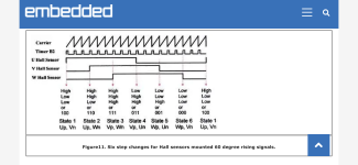
A 60 deg hall commutation scheme looks line this:
E8B14EB0-6B65-4AE9-BF69-AECBD5C68060.png
Do you get hall sensor signals following the pic?
000 (all halls off) or 111 (all halls on)?
If you do then it is a 60deg hall logic.

I think you are possibly confusing hall shift with hall sensor angle. The Votol program has the possibility to shift and match the hall sensor position to the phase firing order. if you set a shift of 60 deg means that controller is firing the phase at another commutation step in the six step cycle, if you set a shift of zero or 120 it’s also a different step.

It’s the same as doing a matching between halls and phases by switching the wires around but it’s done by the software. This is not to confuse with 120deg vs 60deg hall sensor commutation.
 
larsb said:
I think you are possibly confusing hall shift with hall sensor angle. The Votol program has the possibility to shift and match the hall sensor position to the phase firing order. if you set a shift of 60 deg means that controller is firing the phase at another commutation step in the six step cycle, if you set a shift of zero or 120 it’s also a different step.

It’s the same as doing a matching between halls and phases by switching the wires around but it’s done by the software. This is not to confuse with 120deg vs 60deg hall sensor commutation.

Votol software used to has capabilities to match hall angle & firing order in normal situation, but in my case this is different.
I don't know why, maybe factory setting to be the cause of this.

Here is detail of what I'm doing to make it works :
1. Modify the 2nd hall (center Hall sensor) in BLDC hub to be faced down (to make it 60 degree hall angle)
2. Exchange blue & yellow phase wire (via software). I don't know why I have to exchange this wire, but if not then it won't work.
3. Hall sensor degree setting in software is 120 degree (this is funny but works, since actual configuration in motor has already changed to 60 degree. The motor run out of control - run like crazy at full speed and cannot stop until I turn the key off - if I set the setting to 60 degree, rotate smoothly but reverse when I change to -120)
 
Again, that one sensor is flipped doesn’t necessarily mean that you’ve got 60 deg hall commutation. If a sensor needs to flip on 120 deg spaced halls depends on which slot the halls are placed in since each hall switch shall meet the corresponding phase zero crossing/increasing BEMF.
 
Hello

I am new to this forum and need your support,
I bought 72v 50Ah electric chinse Quad which orignlly came pre installed with Votol EM -50s & 1000w motor
I decided to upgrade the controller to EM-150 & didnt get the power I was hoping for.
Next step I ordered 2000w Chinse motor that at the begining controller setup didnt provide the power I hoped for which is spinnig the wheels from dead stop until I changed the deafault 'Flux Weakning' value fom 605% to 20%.
At the moment of change with wheels in the air I could applied full throttle to max speed but the RPM dispaly present up down flactuation (which was exist from first set up of this 2000w motor) so i couldnt tell if the RPM was as with the previous motor, However the when set on the ATV on the road the power was so strong & it blast me forward & the fron wheels almost fliped over had I not hit the brake with brutal force.
After that point I allways get 'Motor Hall' fault when reaching high RPM even if the wheels are in the air or on road the motor allways stall& after it stop I cant applied throttle again until it cut.
I checked the hall sensors, all 3 reach 3.29v when face the magnet then drop to 0, I even opened the motor to check for loose wires or soldering but everything was ok.
If I use the Low speed then the motor doesnt stop with the Motor Hall error.

Please advise if you have any Idea what is the problem
I will add pictures of my setup
Thanks
Have you ever found the problem? I have the same issue with a chinese geared hub motor that worked fine with my previous controller.
 
Back
Top