Mxus 3K temperature sensor help?


Can I Connect this 5volt temp Display to the 5v throttle wire? 😅 i’m not sure if that would mess with the throttle
The working voltage says 5V to 24v

Edit: OK so I gave it a shot and it works perfectly! Hopefully this will help if anyone else is trying to figure this out.
As of now I have the temp sensor connected to the axle and I’m not using the installed temp sensor inside the hub motor because I cannot for the life of me figure out why there’s only one wire coming out. The only thing I can consider is most eBike controllers only need the one wire since it’s already grounded.
 
Here’s some pics how I attached the temp sensor to the axle. It’s working great and it’s actually more accurate than I thought it would be.

First I connected the temp prob to a ring terminal. Then I was able to grind down the ring terminal to slide between the axle flat and the axle nut. Then I proceeded to wrap the temp sensor and ring terminal with copper wiring to the axle to help transfer the heat and to make it sturdy.
 

Attachments

  • AA780FBD-DB35-4789-90EC-5C6D8DD26E2B.jpeg
    AA780FBD-DB35-4789-90EC-5C6D8DD26E2B.jpeg
    308.3 KB · Views: 266
  • F0832604-55C1-4FB7-A027-455AE7EC468B.jpeg
    F0832604-55C1-4FB7-A027-455AE7EC468B.jpeg
    298.3 KB · Views: 266
  • 40620E10-E6C3-4575-BB49-69AC691F2952.jpeg
    40620E10-E6C3-4575-BB49-69AC691F2952.jpeg
    300.9 KB · Views: 266
  • 534CC486-C8A1-4B64-890C-BB2FE9DBB3E1.jpeg
    534CC486-C8A1-4B64-890C-BB2FE9DBB3E1.jpeg
    283.3 KB · Views: 266
Eastwood said:
I’m not using the installed temp sensor inside the hub motor because I cannot for the life of me figure out why there’s only one wire coming out. The only thing I can consider is most eBike controllers only need the one wire since it’s already grounded.
In addition to the phase wires my MXUS had two bunches of 6 wires as shipped
Here's a photo of the MXUS 3k V3 with the resistance measured between the common ground (black wire) and the white wire showing a resistance of 584 ohms at room temperature
I have cooled and warmed the hub and the resistance increases with temperature increase
There is around 7K resistance between red and black (power to hall sensor) and nc to the other wires in the bunch
Temp Sensor.jpg
 
BobBob said:
Eastwood said:
I’m not using the installed temp sensor inside the hub motor because I cannot for the life of me figure out why there’s only one wire coming out. The only thing I can consider is most eBike controllers only need the one wire since it’s already grounded.
In addition to the phase wires my MXUS had two bunches of 6 wires as shipped
Here's a photo of the MXUS 3k V3 with the resistance measured between the common ground (black wire) and the white wire showing a resistance of 780 ohms at room temperature
I have cooled and warmed the hub and the resistance increases with temperature increase
There is around 7K resistance between red and black (power to hall sensor) and nc to the other wires in the bunch
Temp Sensor.jpg

Thanks for the information!
Yeah mine was the same it had two sets of six wires.
I’m guessing the temp display a bought isn’t compatible with the Installed sensor in the hub.
 
Eastwood said:
So I found some pictures of the thermistor installed inside the motor but I still don’t understand why there’s only one wire coming out of the motor?? :| It seems like there would be two wires coming out of the motor like you’re suggesting…
You've already been told the answer:
serious_sam said:
Eastwood said:
the mxus 3k turbo has a white temperature wire built-in. Actually it has two of them because it has two sets of hall sensors. Right now the two white wires are just not connected.
Each set of hall/temp sensors is independent/isolated from the other set. Use one set, forget the other set (that's backup in case you have a failure).
The halls and temp sensor share a common ground. So your temp sensor will be the white and black wires.
 
serious_sam said:
You've already been told the answer:

Right, at first I didn’t understand what AmberWolf was saying but now I get it :wink:


serious_sam said:
The halls and temp sensor share a common ground. So your temp sensor will be the white and black wires.

Great, makes since now, thanks! :D

Please note I’m a newbie with electronics. I have lots of experience fabricating, building bikes, motorcycles, Engine work etc. Still learning the Electric stuff :wink:
Thanks to endless sphere as I have learned so much information! Very grateful for this online forum!
 
Eastwood said:
Can I Connect this 5volt temp Display to the 5v throttle wire? 😅 i’m not sure if that would mess with the throttle
The working voltage says 5V to 24v
Since you are already running two wires (temp sensor signal, and ground) from the hall / sensor cable, you can just use the 5v wire from there.

As of now I have the temp sensor connected to the axle and I’m not using the installed temp sensor inside the hub motor because I cannot for the life of me figure out why there’s only one wire coming out. The only thing I can consider is most eBike controllers only need the one wire since it’s already grounded.

There's two wires. The ground, and the sensor "signal".

You connect both wires to anything that needs to read that signal.
 
Eastwood said:
amberwolf said:
Eastwood said:
-
Well the white wire coming from the motor it’s just a single wire. Well there are two sets of hall sensors and they both include the white wire... but maybe the ground wire is just left in the hub and only the white wire comes out?

No, the ground of the *entire* sensor/signal cable is shared among *all* sensors/signals in the entire cable.

So you have to split that ground so the controller gets one and so does the temperature monitor.

What ground wire would I split since there’s no ground wire coming from the motor?
There is--it's the same ground wire that is used for hall sensors. it is shared between all sensors and signals in the entire cable.


Note also that as I said before, some very few motors use the 5v wire instead of the ground wire for the other temperature sensor wire...if you get no ohms reading on the sensor using the ground wire and the sensor wire, then try the 5v wire and the sensor wire.

When you find the pair of wires that gives you an ohms reading (which changes with temperature) then you use those wires on your monitoring unit, in place of the sensor that it already has on it most likely. (unless it specifically says it can monitor two separate sensors with two separate readings, then you would have to disconnect the built in one to use an external).

If you don't get the right reading on the temperature, then you would have to calibrate the display with the motor's sensor. If it can't be calibrated, then it can't be used with the built in motor sensor; there are dozens, probably hundreds or thousands of different kinds of sensors and they all give different readings for temperature in different ways.
 
It seems to be a PTC thermistor, as the resistance increased when I heated the hub rather than decreasing
Unfortunately the slope and offset can vary and it's not linear
The reading at ambient (22 Deg C 72F) is 584 ohms
It isn't a thermocouple on the MXUS and both wires are black from your display so that isn't one either so you have half a chance of getting a reading but a good chance it may be wrong. You may also find it only registers at all when the motor is hot but it may be useable if you know how the display relates to the actual temperature (use brain for calibration)

I might suggest double checking that there is low resistance between the throttle wire supply and the red wire that goes to the hall sensors? (check for a low resistance between the two unpowered)
If it's low resistance it 's a common 5V rather than an isolated one (sometimes used to avoid interference)
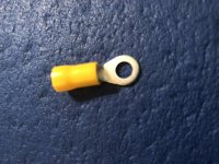
The other thing to be sure of is which pole is positive coming out of the display. both wires on the existing (axle) probe are black because it doesn't matter but it will only work one way connecting to the hub sensor.
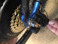
With the new (axle) sensor powered up, check the voltage to each wire of the sensor.
The white wire from the MXUS should connect to the low voltage side of your new axle sensor display
Peer review / sanity check - it's a bit late here

I tried short circuiting my MUXUS to heat it but as it's 0.22 ohm resistnance my benchtop PSU did nothing feeding it 10W.
A hot air gun got a rise from 573 to 584 ohm but who knows what the coil temperatures were
Couldn't fit it in the oven. Partner will not be amused if it falls of the hot water tank in the middle of the night so working on other methods of calibration :)
 
Back
Top