
dabeindan
1 mW
This is my very first e-bike build. As a total novice I just wanted to share my experiences and provide some details of the kit I bought from BMSBATTERY.COM. Maybe the photos can help answer some questions, and at the same time perhaps someone can provide suggestions or tips on a better way of doing things.
I am in no way promoting bmsbattery, nor do I have any association with them. I picked them because of low cost, and in many ways you get what you pay for.
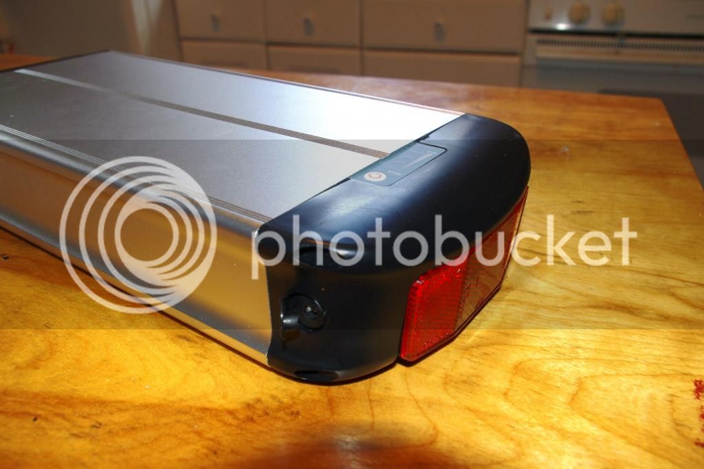
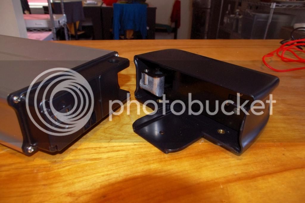
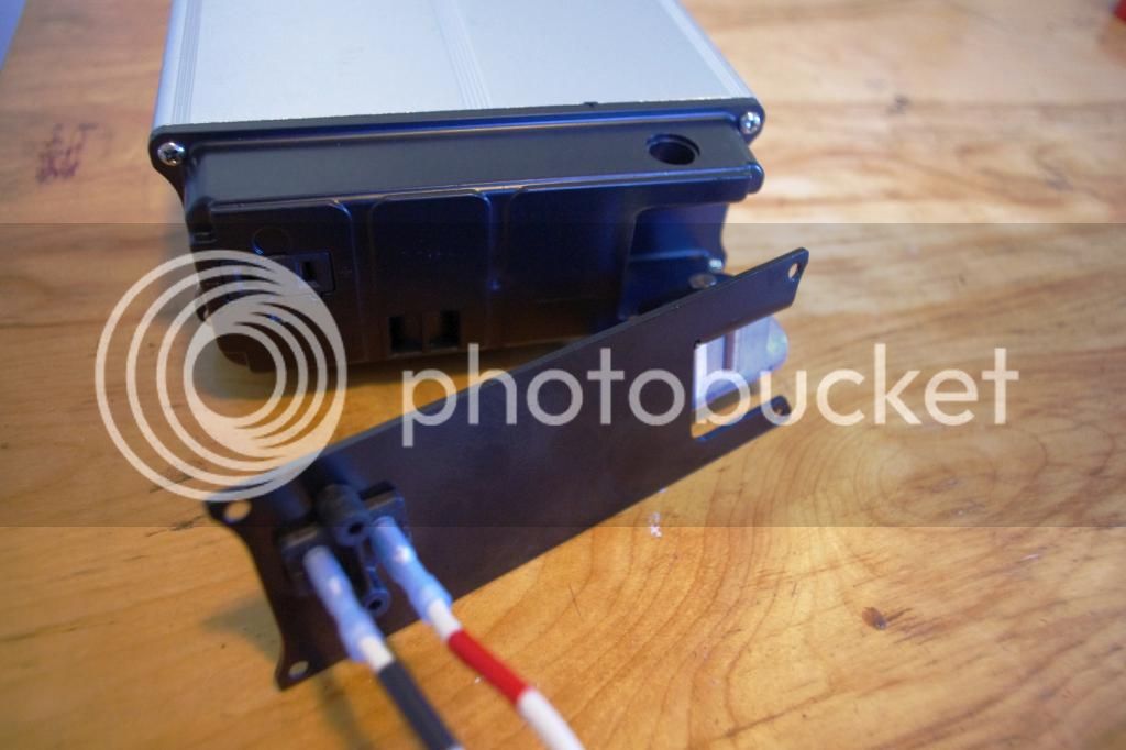
Battery is a 36v, 12ah LiFePO4 in an alloy casing. 2 poles (+/-), lock is just mechanical and no on/off switch.
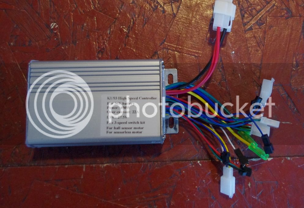
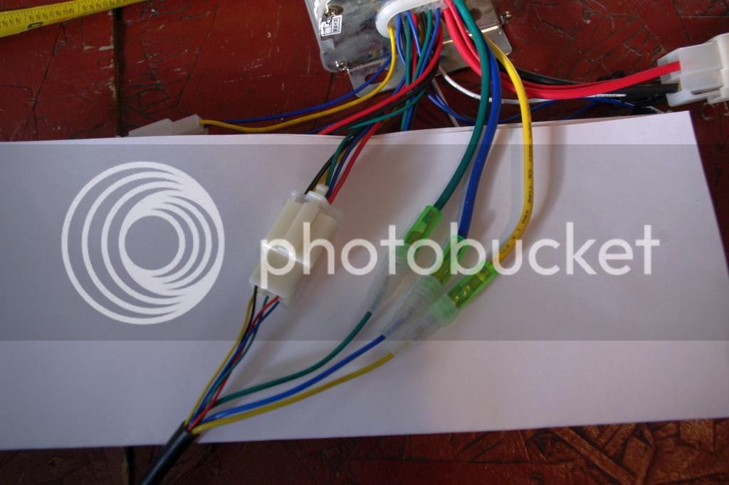
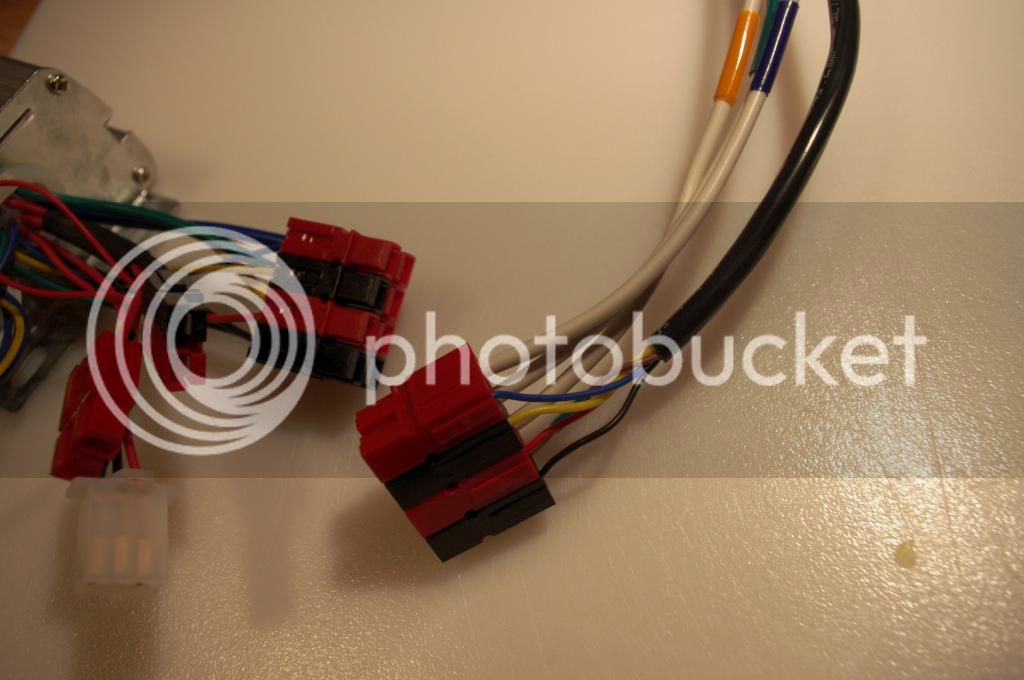
Controller with the battery wires on top of photo, thick red, thick black, thin red. I had questions on the thin red wire and how to connect to the battery (only two wires). See my other post titled "BMSBATTERY kit - Battery to Controller question" and advice from Dnmun, Dogman and d8veh (thank you all).
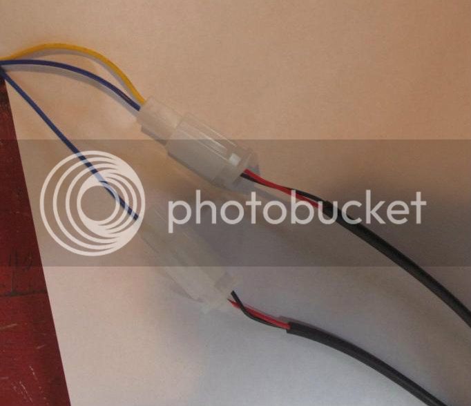
Brake cables connected to the controller, brake wires on the lower side of picture, and controller side on the upper. Notice that one set on the controller side wire is a single wire and the other has two wires. In testing the only one worked was the brake level connected to the double controller wire, not the single side. Is this by design? Or did I not connect something correctly? Or is this controller faulty?
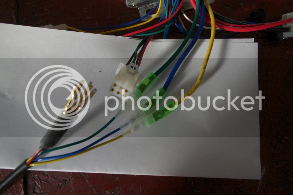
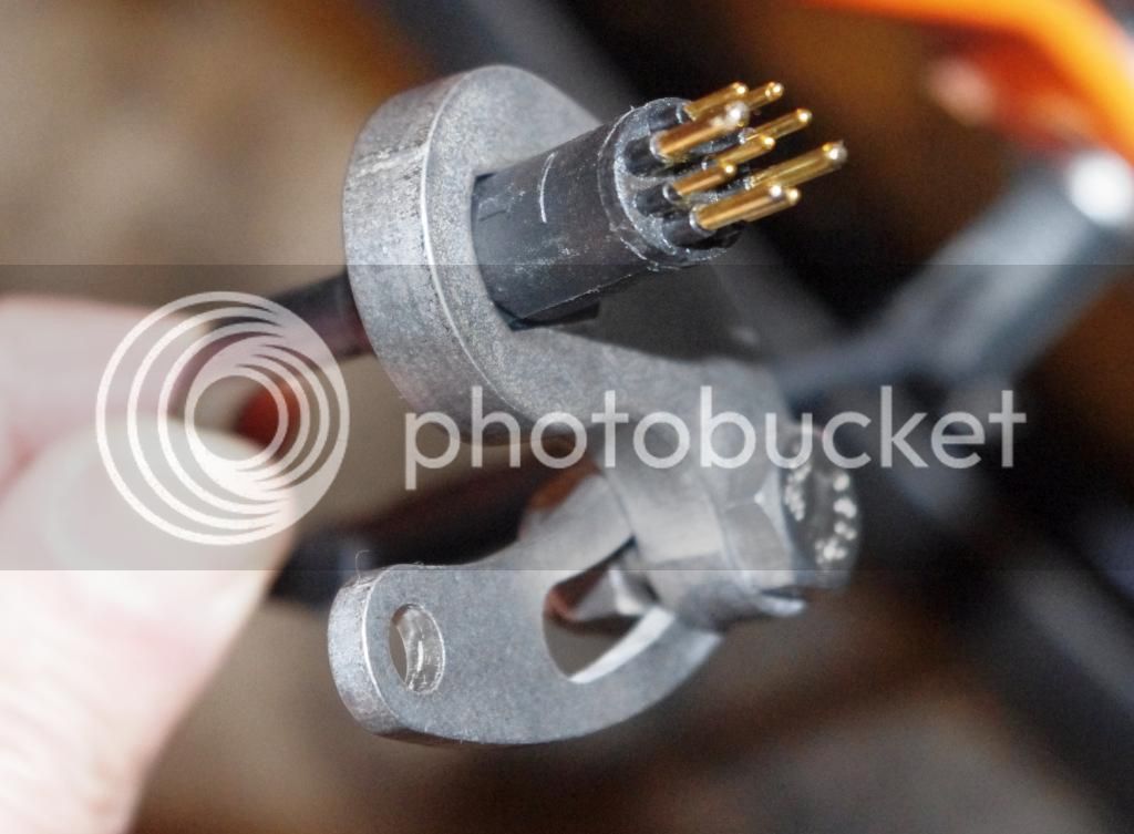
Motor wires (three thick) and hall sensor wires (5 thin) – it came uncoupled on the motor side (lower side of pic); I had to match and insert into the supplied blank connector.
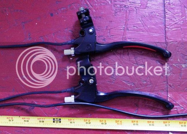
Brake levers wires at 60 inches.
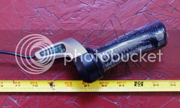
Throttle wires at 78 inches. Throttle with no on/off switch, but has battery indicators. (I later used a different one with an on/off switch)
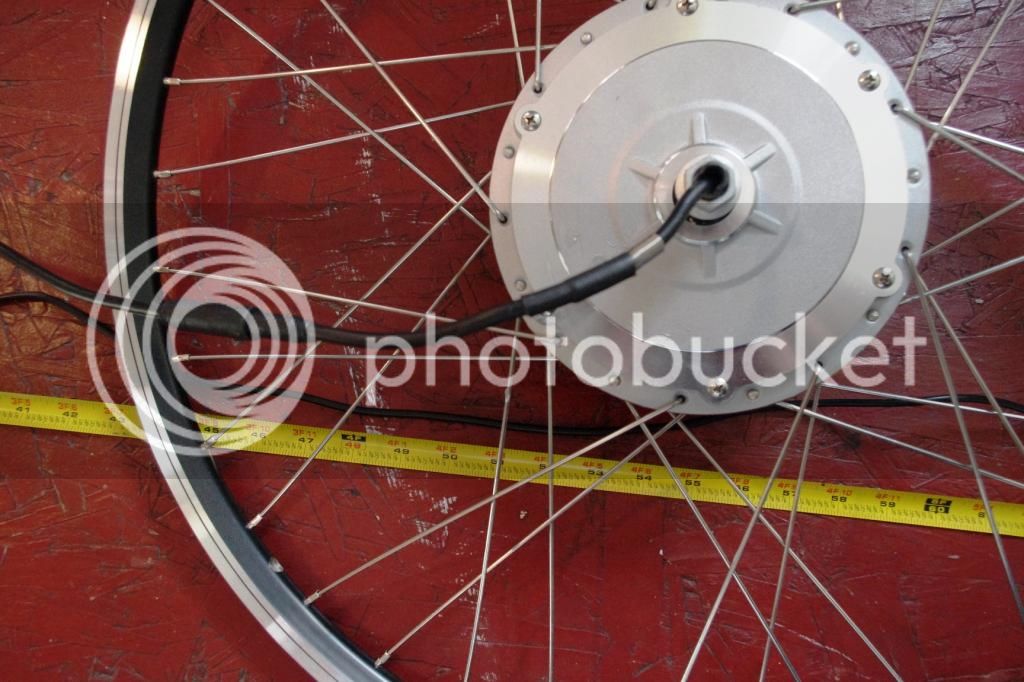
Front motor and cable length at only 54 inches. 36v 350 watts disc compatible BaFang motor. Shouldn’t all wires be similar length? This shorter motor cable proofed to be a real pain later.
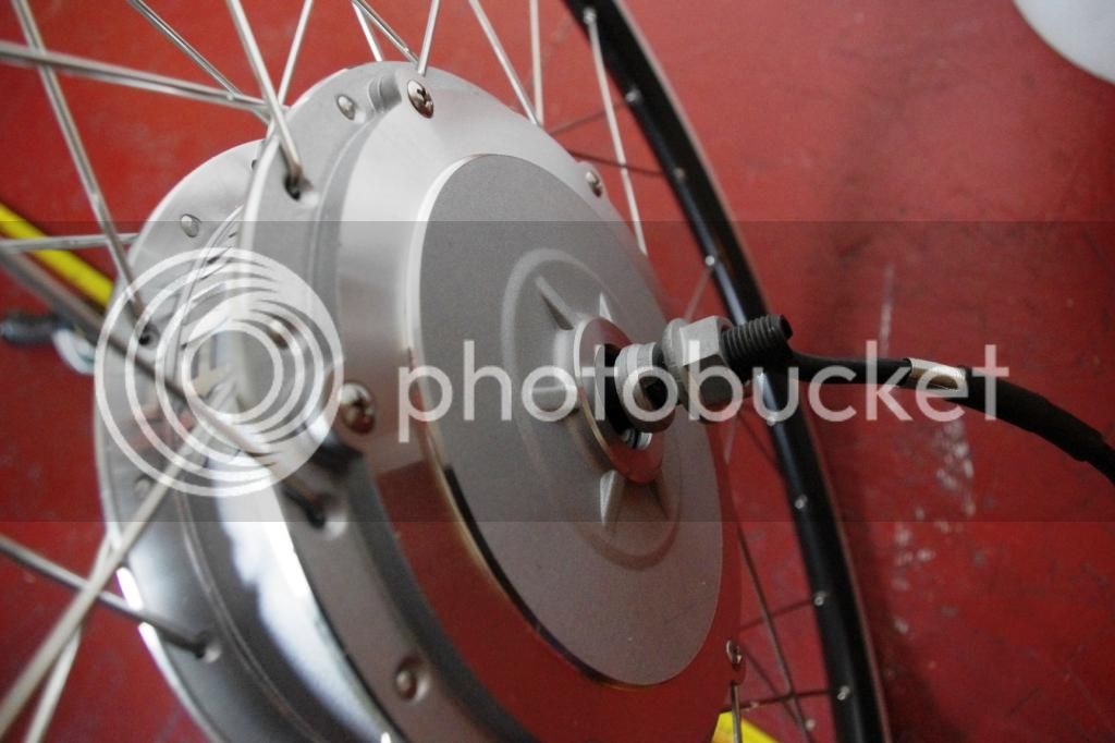
Front motor (right side) with a washer, anti-torque washer, nut.
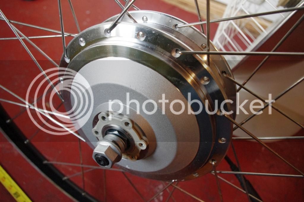
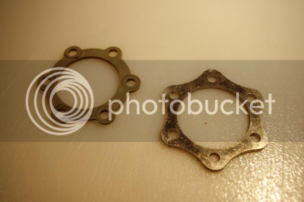
Disc side with similar setup of washers, nut, etc. and a plastic disc spacer. Plastic???
Didn’t like the idea of a plastic disc spacer, I bought a metal disc spacer from ebike.ca (right) pic. For this setup I ended up not needing the spacer, but depending on the brake caliper I may need in the future. I did get the disc brake calipers and discs from BMSBATTERY (not pictured), they are functional but crude and badly engineered. Will upgrade to Avid BB7 185mm front and rear soon.
In measuring cable length, the motor cable was short by 6inches, thus had to extend all 8 wires. This was a major pain in the rear end. I re-did all the ends with Anderson power poles.
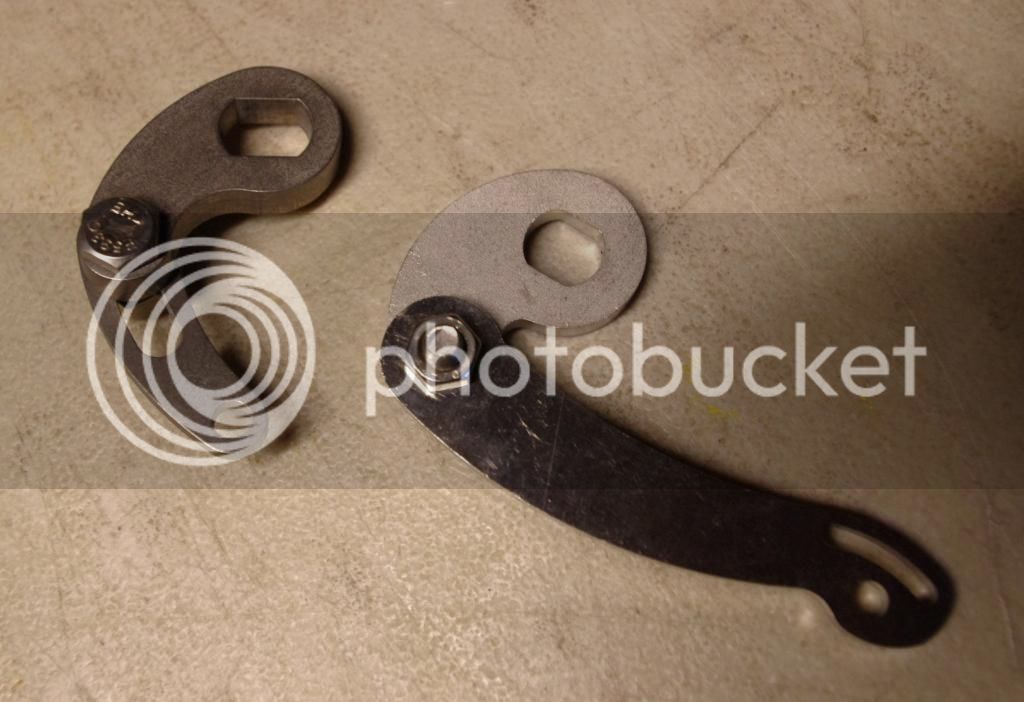
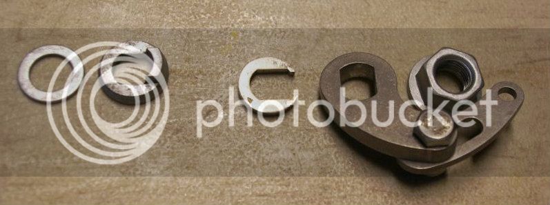
The left anti-torque is from ebike.ca (thicker). The thinner arm on the right was from BMSBATTERY. The ebike.ca unit also utilizes the fork’s braze-on, as suppose to the BMSBATTERY’s hose clamp to fork setup.
Exploded view of the order of the washers on the right side – washer, anti-torque washer, (then fork), c washer to clear the lawyers tab on the fork, torque arm, nut. The C washers are from ebike.ca.
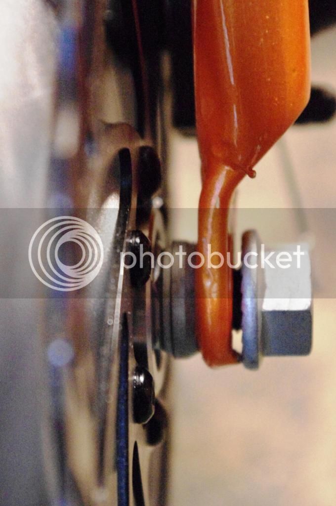
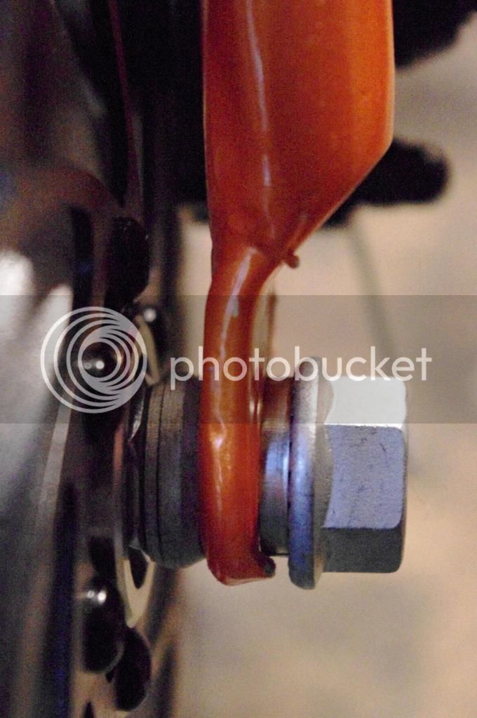
Notice the gap caused by the lawyer’s tab before the C washer, then with C washer
Notice how the axle on the disc side is barely long enough; certainly not long enough to accommodate the anti-torque arm. Thus the arm has to be on the right (cable) side.
Fortunately for me that the motor cable connector does fit through the opening of the anti-torque arm.
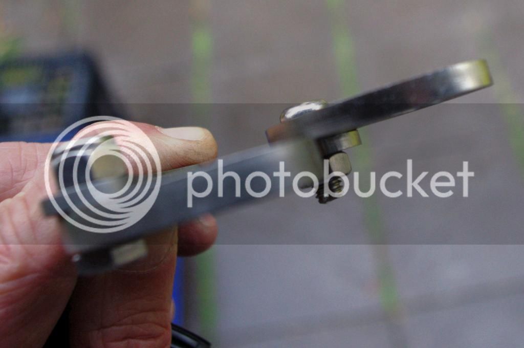
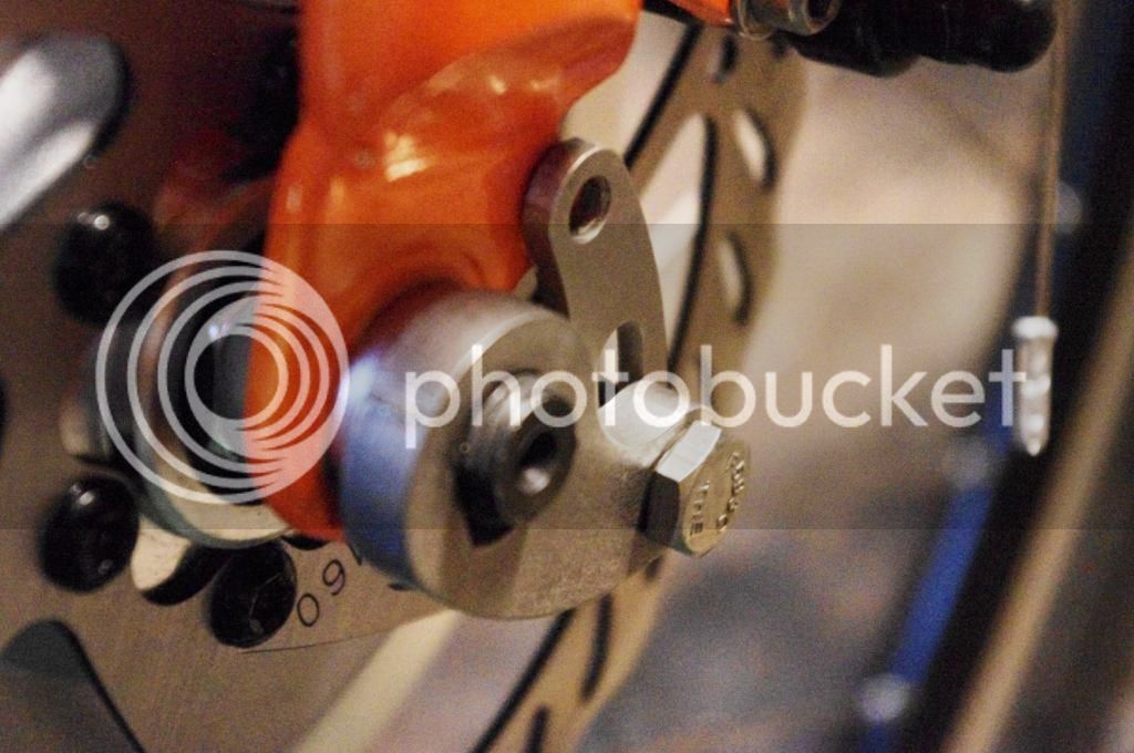
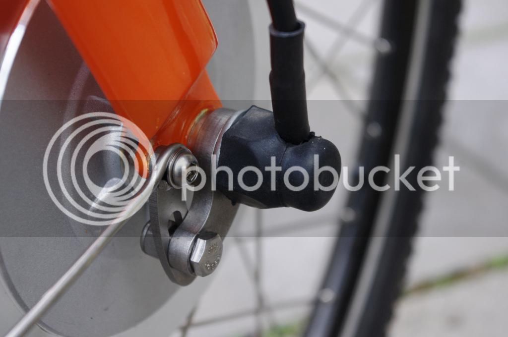
Detail pic of the anti-torque arm, mounted onto the braze-on eyelet. I just read on the forum motor is mounted up side down, need to run the cable down to create a water drip loop.
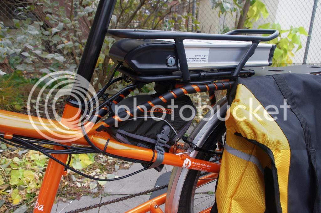
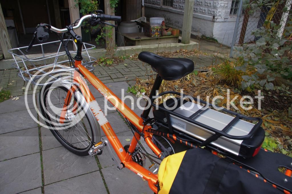
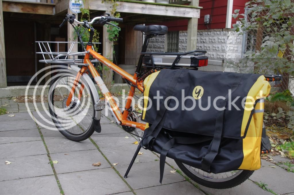
Battery is mounted in the rear rack that came with the kit, to mount on top of the Yuba rack I cut the legs off and used seat stays and P clamps to mount. The controller and the extra wires all fit (crammed) inside the large seat wedge pack, now mounted below the battery. I have mixed feelings about the battery mount location; I may relocate it inside the pannier in the near future.
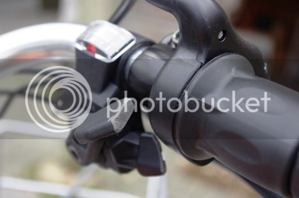
Ended up using a different throttle with an on/off switch, but all the extra bulk meant I had to mount it pointing it away from me. I will have to find a different setup but this will do for now.
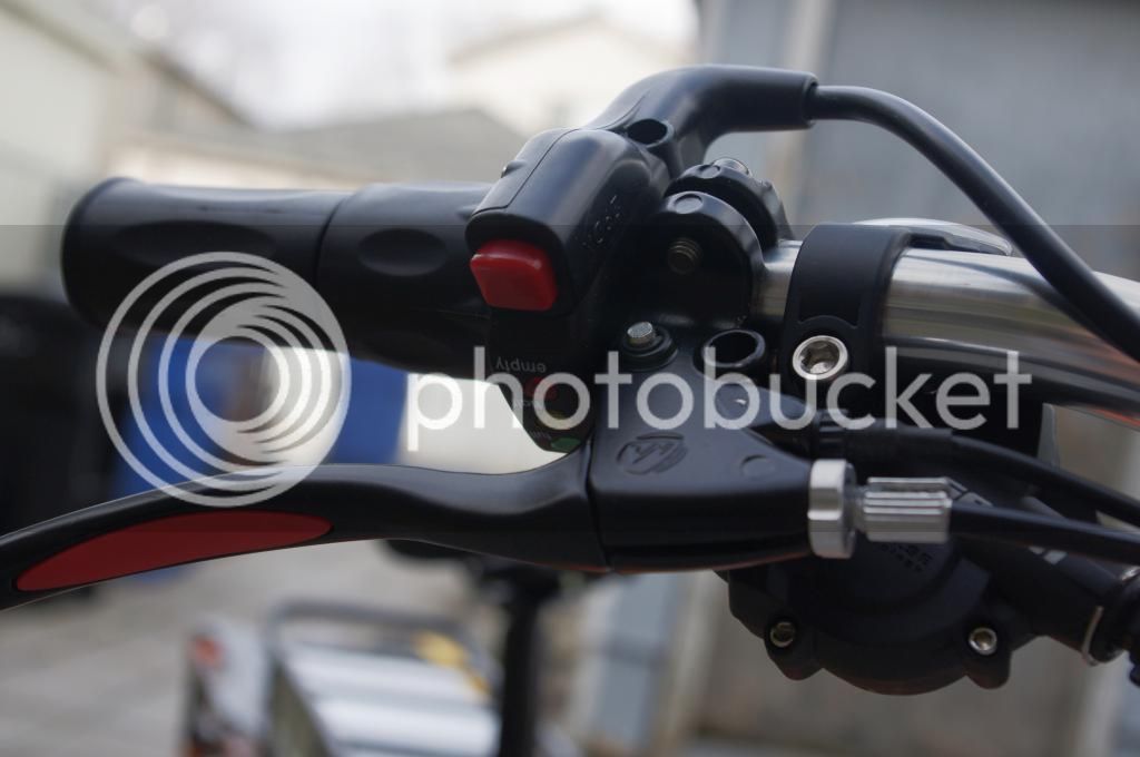
Shifter levers also had to be trimmed to clear the throttle body.
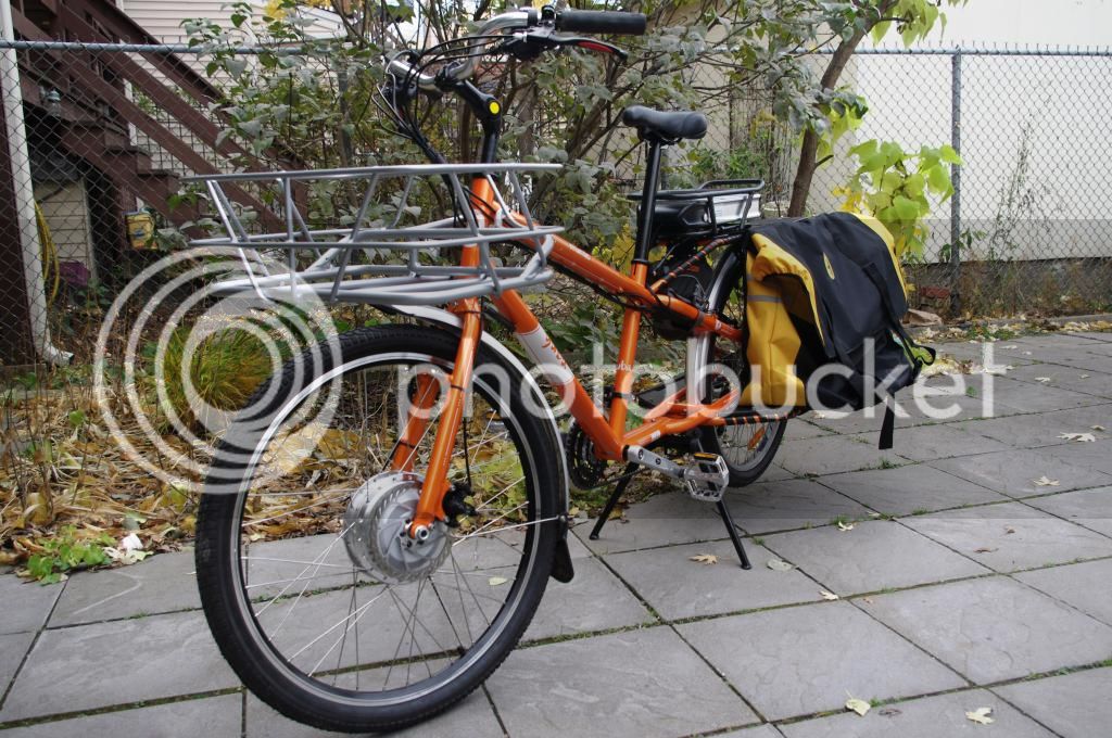
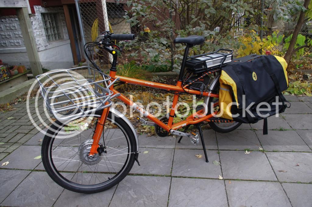
Here are some pictures of the finished bike, rev 1 anyways.
Initial ride was good, but will have to live with it for a little bit before I truly know. Will post results in a few weeks. Feel free to ask questions or give suggestions, but just realize that I am no expert and can only tell you what I did, rather than what's the correct way of doing things; this is especially true when it comes to wiring.
I am in no way promoting bmsbattery, nor do I have any association with them. I picked them because of low cost, and in many ways you get what you pay for.
Battery is a 36v, 12ah LiFePO4 in an alloy casing. 2 poles (+/-), lock is just mechanical and no on/off switch.
Controller with the battery wires on top of photo, thick red, thick black, thin red. I had questions on the thin red wire and how to connect to the battery (only two wires). See my other post titled "BMSBATTERY kit - Battery to Controller question" and advice from Dnmun, Dogman and d8veh (thank you all).
Brake cables connected to the controller, brake wires on the lower side of picture, and controller side on the upper. Notice that one set on the controller side wire is a single wire and the other has two wires. In testing the only one worked was the brake level connected to the double controller wire, not the single side. Is this by design? Or did I not connect something correctly? Or is this controller faulty?
Motor wires (three thick) and hall sensor wires (5 thin) – it came uncoupled on the motor side (lower side of pic); I had to match and insert into the supplied blank connector.
Brake levers wires at 60 inches.
Throttle wires at 78 inches. Throttle with no on/off switch, but has battery indicators. (I later used a different one with an on/off switch)
Front motor and cable length at only 54 inches. 36v 350 watts disc compatible BaFang motor. Shouldn’t all wires be similar length? This shorter motor cable proofed to be a real pain later.
Front motor (right side) with a washer, anti-torque washer, nut.
Disc side with similar setup of washers, nut, etc. and a plastic disc spacer. Plastic???
Didn’t like the idea of a plastic disc spacer, I bought a metal disc spacer from ebike.ca (right) pic. For this setup I ended up not needing the spacer, but depending on the brake caliper I may need in the future. I did get the disc brake calipers and discs from BMSBATTERY (not pictured), they are functional but crude and badly engineered. Will upgrade to Avid BB7 185mm front and rear soon.
In measuring cable length, the motor cable was short by 6inches, thus had to extend all 8 wires. This was a major pain in the rear end. I re-did all the ends with Anderson power poles.
The left anti-torque is from ebike.ca (thicker). The thinner arm on the right was from BMSBATTERY. The ebike.ca unit also utilizes the fork’s braze-on, as suppose to the BMSBATTERY’s hose clamp to fork setup.
Exploded view of the order of the washers on the right side – washer, anti-torque washer, (then fork), c washer to clear the lawyers tab on the fork, torque arm, nut. The C washers are from ebike.ca.
Notice the gap caused by the lawyer’s tab before the C washer, then with C washer
Notice how the axle on the disc side is barely long enough; certainly not long enough to accommodate the anti-torque arm. Thus the arm has to be on the right (cable) side.
Fortunately for me that the motor cable connector does fit through the opening of the anti-torque arm.
Detail pic of the anti-torque arm, mounted onto the braze-on eyelet. I just read on the forum motor is mounted up side down, need to run the cable down to create a water drip loop.
Battery is mounted in the rear rack that came with the kit, to mount on top of the Yuba rack I cut the legs off and used seat stays and P clamps to mount. The controller and the extra wires all fit (crammed) inside the large seat wedge pack, now mounted below the battery. I have mixed feelings about the battery mount location; I may relocate it inside the pannier in the near future.
Ended up using a different throttle with an on/off switch, but all the extra bulk meant I had to mount it pointing it away from me. I will have to find a different setup but this will do for now.
Shifter levers also had to be trimmed to clear the throttle body.
Here are some pictures of the finished bike, rev 1 anyways.
Initial ride was good, but will have to live with it for a little bit before I truly know. Will post results in a few weeks. Feel free to ask questions or give suggestions, but just realize that I am no expert and can only tell you what I did, rather than what's the correct way of doing things; this is especially true when it comes to wiring.
