My first EV conversion: '69 Honda CA160 "Baby Dream"

Can anyone double check my wiring diagram? :confused: (Plagarized from another build here on endless-sphere, but adjusted for my build and with a contactor with a 12v coil)

72v-wiring-diagram.png
 
Elektrosherpa said:
I dont see it...

The picture or the resistor?

The resistor is connected in parallel with the contactor and feeds both the B+ and and what I guess is the logic input (7)

Maybe the controller will turn off completely when the voltage goes too low, but I think it is a risk that the controller will pull current trough the resistor and possibly heat up the resistor to dangerous levels.
Or just use unnecessary current when doing nothing
 
So I need a third switch in series with the precharge resistor?

Here's another image of my draft wiring diagram, coming from a different server:

stn7072ij0t81.png
 
j bjork said:
Elektrosherpa said:
I dont see it...

The picture or the resistor?

I didnt see the picture.
Now I see it twice (in the first post and in the last one, too).

And I agree-there is a switch missing, which activates the precharge.
This is the concerned section of my wiring:
Kelly-WiringPlan-ManualSwitches.jpg
 
Thank you very much!! I'm glad I asked :)

What if the kill switch was on the purple wire? The power wire to the #7 pin on the controller? [edit: answer is no, because that wire is 72v and the switch is only good for 12v. Back to the original problem!]

That wouldn't close the contactor but it would shut of the controller.

I would like to have just two switches, if possible. I can't think of a good place on my bike to add a third switch.
 
Elektrosherpa, you don't use a contactor at all? [edit: I found your build thread and I can see that you're using two battery switches instead. Lots of good reading in that thread :)]
 
guess I'll have to find a spot. I want to make this bike pretty user friendly since it will be for my wife to ride
 
I started wiring the throttle. There's 6 wiring coming out of the throttle, three for the throttle itself and three for the switch that I'm planning on using for the turn signals. And holy hell are the wires tiny!

PXL_20220408_012912510.jpg


Working with wires this small really sucks. The wires that I bought to build the wiring harness are 16 gauge, and these tiny wires must be like 24 gauge. So making a connection between the two sizes is tricky.

The first connector I tried was a crimp on connector with a heat-shrink layer around it. I think I got it connected fairly well, but I really needed to squeeze hard on the side with the smaller wire. And then when I used a heat gun to shrink the heat-shrink, it exposed cuts that I accidentally made with the pliers.

PXL_20220408_020058911.jpg


And you REALLY don't want these wires to short out, because if they do then the motor controller will see the full 5v which is WIDE OPEN THROTTLE! (This is also why the kill switch is important).

So I cut off those connectors and tried another one: a heat shrink tube with a low-temp solder ring. This worked really well.

PXL_20220408_015918916.jpg


My next challenge is to get the other end of the wire into the connector that plugs into the motor controller. They gave me all the little parts so assemble it myself. Going to be fun. :rolleyes:

PXL_20220408_020731917.jpg


So that is as far as I got. Not very far!
 
Alright I think I have fixed the problems in my first draft of the wiring. In addition to the drain via the precharge resistor, I had also mistakenly used my ignition switch (originally for a 6v bike) for the 72v low-current wire between the battery and the DC-to-DC converter.

Here's the 2nd draft. Please let me know if you see anything wrong, and is it OK to put an LED in series with the contactor coil wiring ?

72v-wiring-diagram-v2.png
 
mannydantyla said:
Alright I think I have fixed the problems in my first draft of the wiring. In addition to the drain via the precharge resistor, I had also mistakenly used my ignition switch (originally for a 6v bike) for the 72v low-current wire between the battery and the DC-to-DC converter.

Here's the 2nd draft. Please let me know if you see anything wrong, and is it OK to put an LED in series with the contactor coil wiring ?

72v-wiring-diagram-v2.png

No you can not put led there it causes voltage drop and limits current to the contactor coil.
Otherwise it is probably alright something that catches my eye is that kelly powerline (purple). Without knowing much of kelly controllers or their internal wirings i hope its okay to feed powerline before main power is available.
 
Thank you kuoppis, I will move the status LED to somewhere else. It just bother's me that there is no status indicator from the controller, other than beeping codes if there's an error. The reason I originally put the LED in series with contactor coil is it would indicate that the contactor was closed or open. And therefor the bike was on or off.

I'm digging through the user manual and it doesn't say anything about providing power to B+ before power to pin 7. It only says "Battery voltage can be used for controller supply."

Maybe I could move the LED to the 12v output supplied by the controller (pin 11)? But would that light up when pin 11 (the purple wire) gets power, but not B+? Only one way to find out.
 
If you want a led that shows if the contactor is closed or open you could put it in parallel with the "protection diode".
You also need the appropriate resistor in series with the led to limit the current flowing trough it (something like 10-20mA).

You cant have all the current for the contactor flowing trough the led like in your diagram.

Is there a reason to have an extra kill switch? Is it easier to reach or find that the key switch?
If I wanted to make a bike easy to use for someone else I would go for automatic pre charge and just a key switch to turn on and go.
 
Thank you bjork! I'll give that LED idea a try.

And for the kill switch, yeah my ignition switch (key switch) is very strange, it is not just on and off, it has like 5 positions! Apparently Mr. Honda wanted riders to be able to turn the head light on a remove the key, or have the key in with the bike off but unable to pull it out. And everything in between. I still don't know what they all are.

So I figured that could be difficult to manage in an emergency situation. It's also located in a spot that isn't great to reach while riding, it's by the headlight bulb. Not the worst but not the best.

However I just learned that the Kelly controller has a pretty good feature that would negate the main reason for a kill switch: the throttle only goes up to 4.5v and if it ever shows 5v then the controller will now that there is a fault and to stop the motor.

I might also be able to wire up the brake light switches to act as a kill switch...? Maybe. Might need a relay.

But I already have the kill switch mounted to the handlebars so I am going to use it for now.
 
I got the motor spinning and the motor controller is all configured!
I was dreading using the Kelly config software but it wasn't too bad thanks to this Endless Sphere discussion and these youtube videos.

Here is a video of it that I have uploaded to Reddit: https://www.reddit.com/r/EVConversion/comments/u4glw0/got_it_spinning_thanks_everyone_for_you_help_i/

Here are my notes:

Steps to program the controller:

  1. Wire up everything but have the contactor switched off
  2. connect the battery ground to B-
  3. switch on the contactor
  4. ensure that the motor turns when the throttle is lightly applied, in either direction
  5. open the program and connect to the controller (will take a few tries?)
  6. set all the motor parameters (# of poles, etc)
  7. set the identification angle to 170
  8. save:
    • write
    • read again and check that its still there
    • quit the program
    • disconnect the battery
    • wait 3+ seconds
    • connect the battery again
  9. the motor should begin moving, this is the identification angle function working
  10. wait about three minutes and wait until you hear a beeping noise from the control. This is the "reset error" telling you that it needs to be reset again. You can connect to the bluetooth adapter with the app to verify this error code.
  11. disconnect the battery from the controller and wait 3+ seconds
  12. reconnect battery
  13. open config program
  14. read the parameters
  15. check that the identification angle has been changed to 85
  16. check that the motor turns when given throttle
  17. check full speed!
  18. set all the vehicle parameters in the config software, save, reset, etc.

I found that when I got to step 4, the throttle would not cause the motor to spin. This worried me, but I discovered that it was because the "three way switch" option was enabled. And neither pins for reverse or forward were getting 12v, so it assumed neutral and therefor did not spin the motor.

How to use the bluetooth adapter and Kelly's AC Aduser android app:

  1. scan for bluetooth devices before powering up the controller
  2. power up the controller
  3. scan for bluetooth devices again and look for a new one, it might be labelled 20102202 or something
  4. the PIN is 1234
  5. open the AC Aduser app
  6. select Bluetooth com
  7. connect by pressing the leftmost black button, then tap the numbers
  8. press the 3rd button from the left, to read
  9. change the parameters where needed
  10. press the rightmost button for write
  11. press the 2nd to left button, to disconnect

Here are some of my parameters that I configured:

  • set the nominal motor current to 90 (this is used by the angle identification function).
  • set the battery current limit to 60%. My battery can do 60 amps continuous, the controller can do 100 amps continuous. The rest of the math is pretty simple.
  • max speed can be set to 1140 - because that’s max rpm of my motor. FYI 1140rpm for a ~23 inch diameter wheel will give me a theoretical top speed of 78 mph. I'll want to balance the rear wheel before I do anything near that!
  • accell time should be 10 (thousands of a second)
  • keep these as set up from factory: torque speed kp, torque speed kj, speed error limit
 
Anybody know of a good way to balance a wheel with a hub motor? The hub motor makes the normal method not possible
 
It's been a while but last April I got the motor controller programmed and the motor/wheel is spinning great! Video.

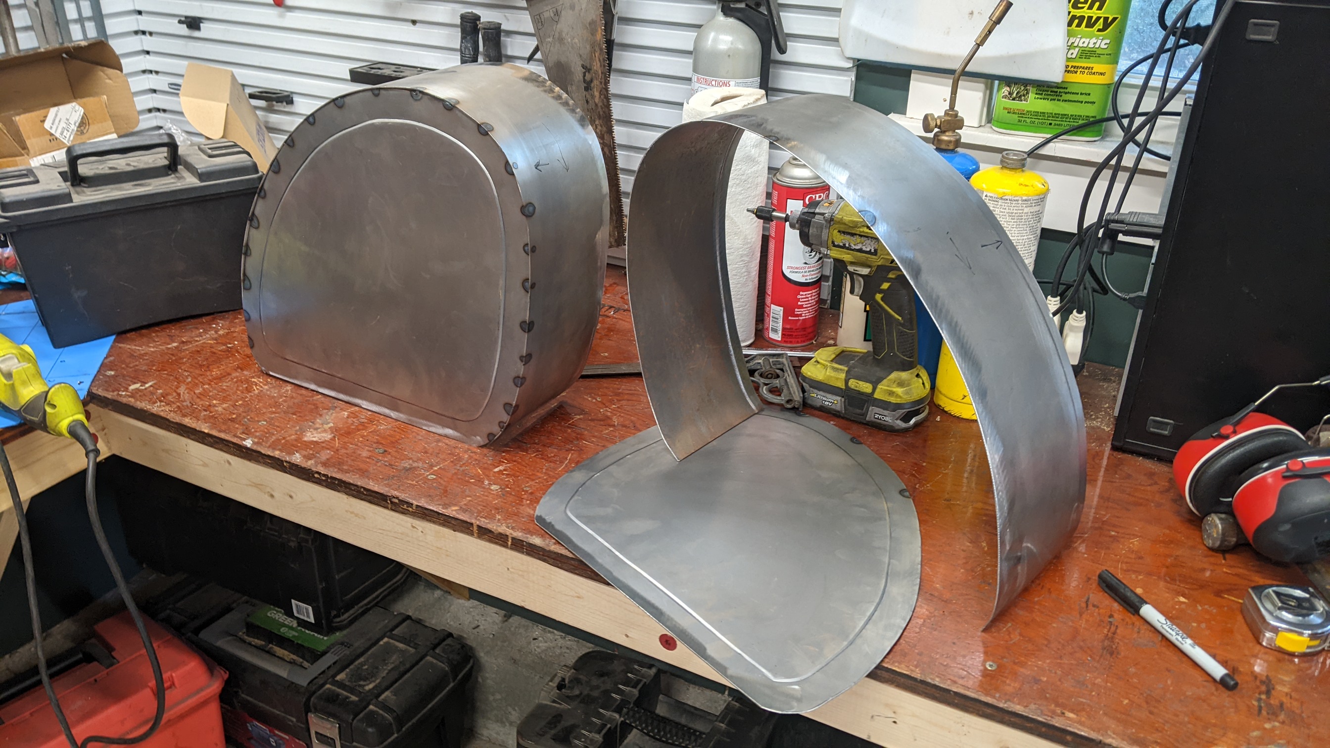
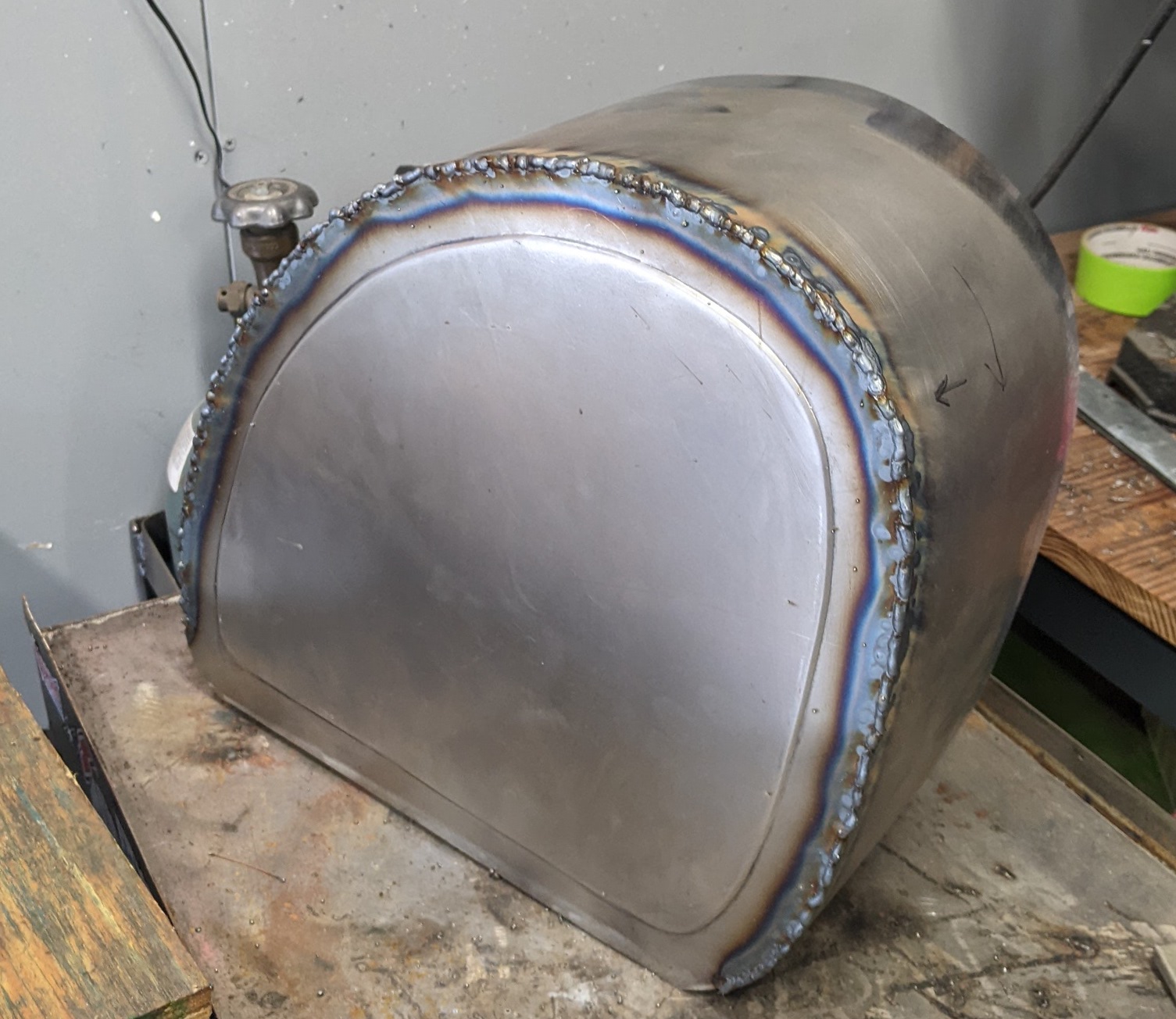
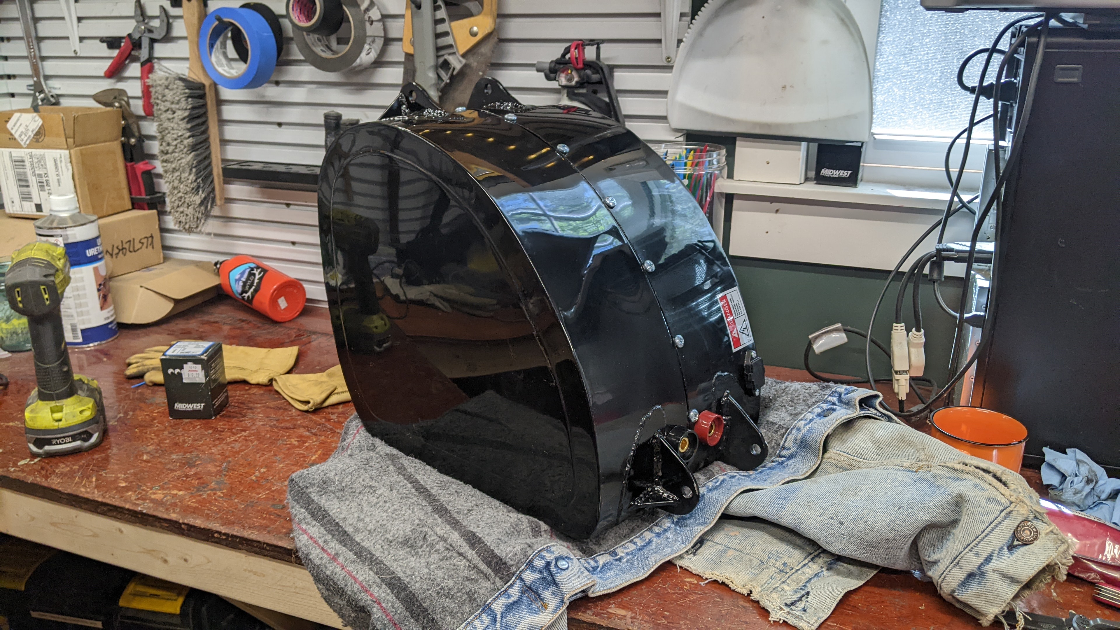
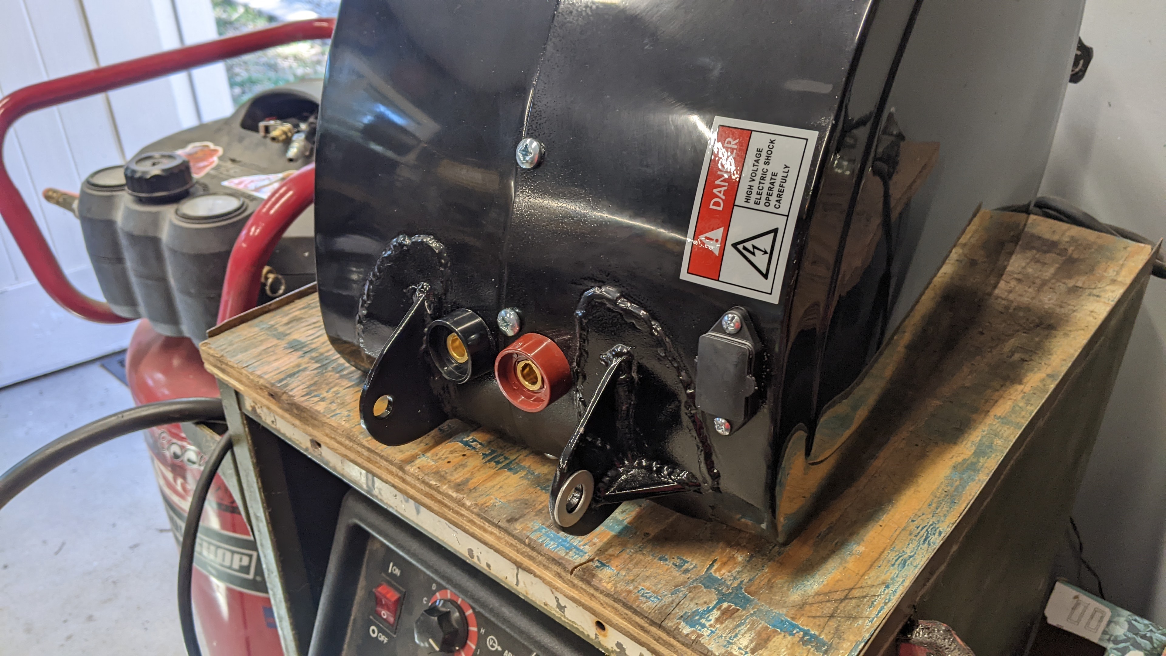
Here's the progress on the battery enclosure. It's nearly ready for paint!


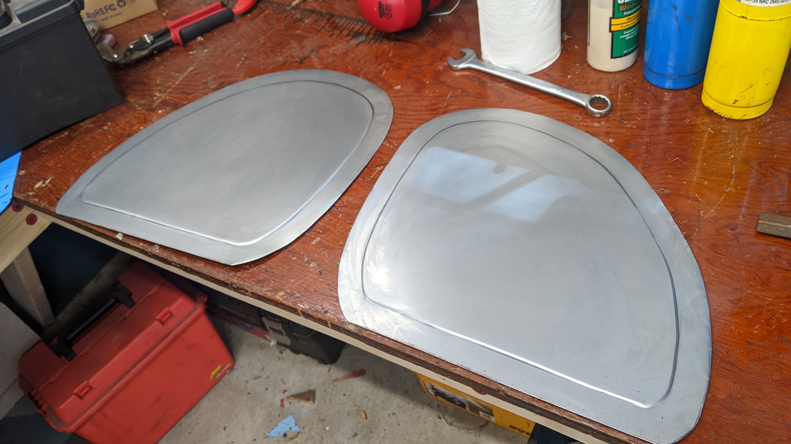
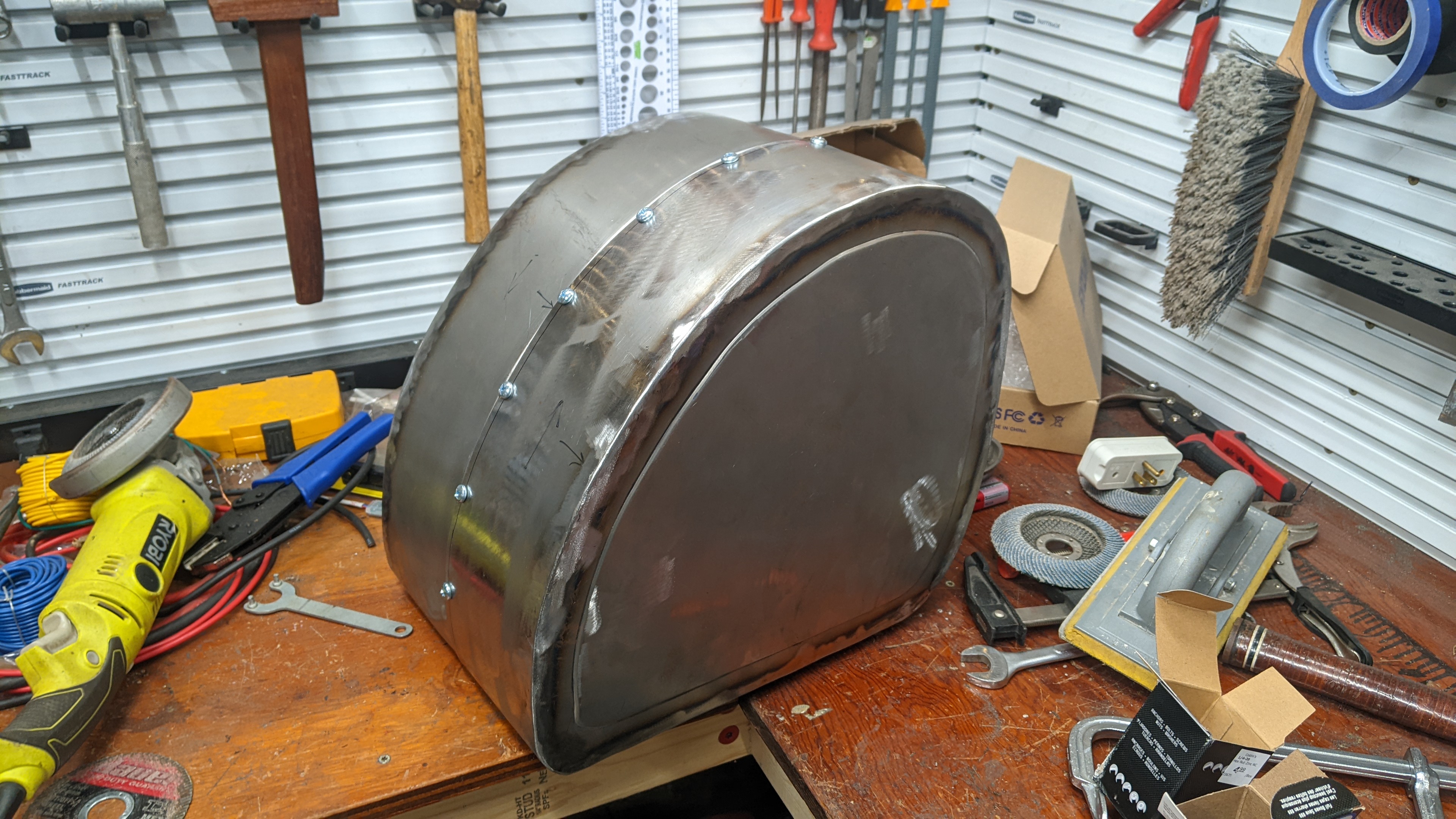
I used a bead roller to create the step bead.


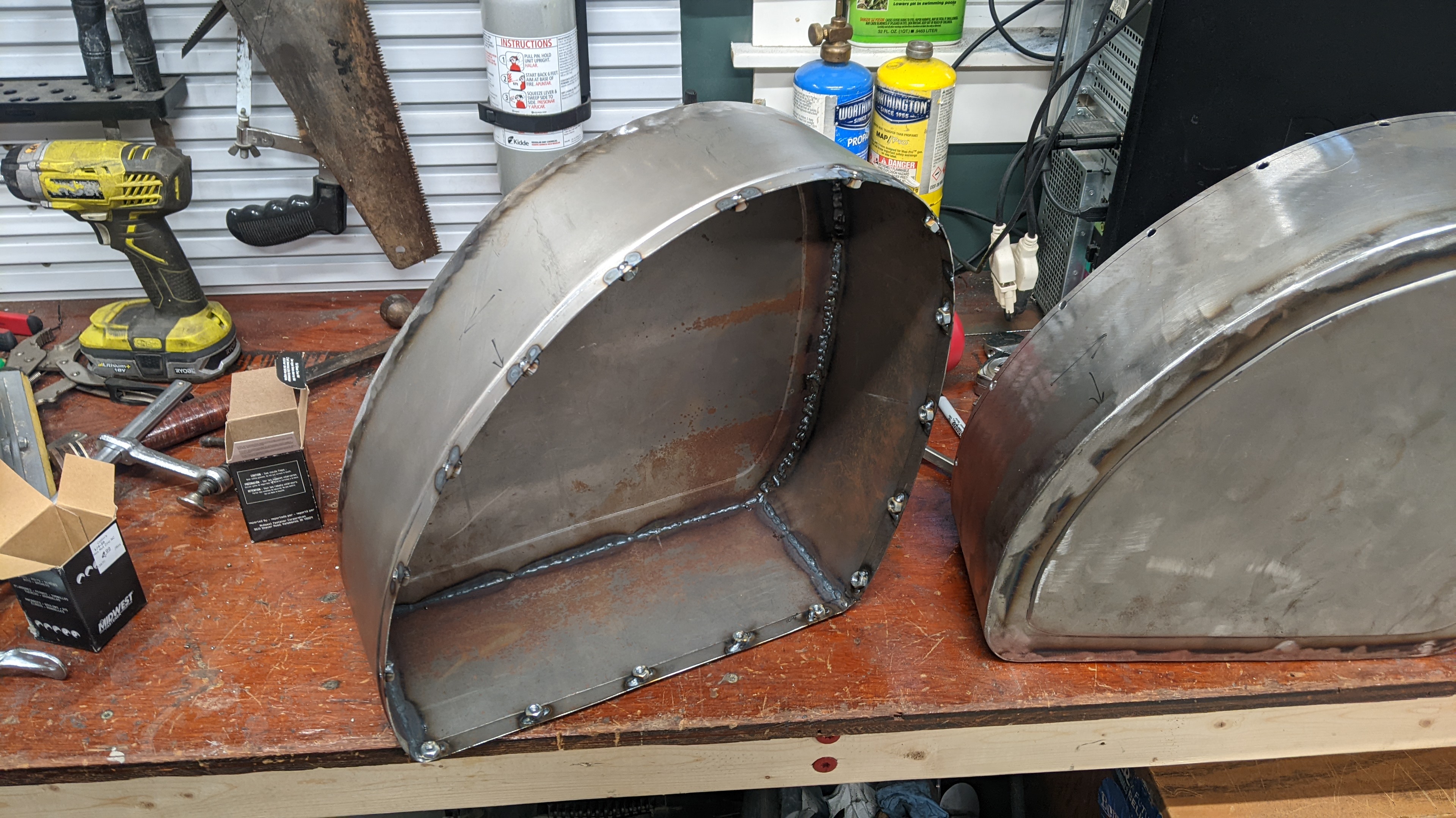
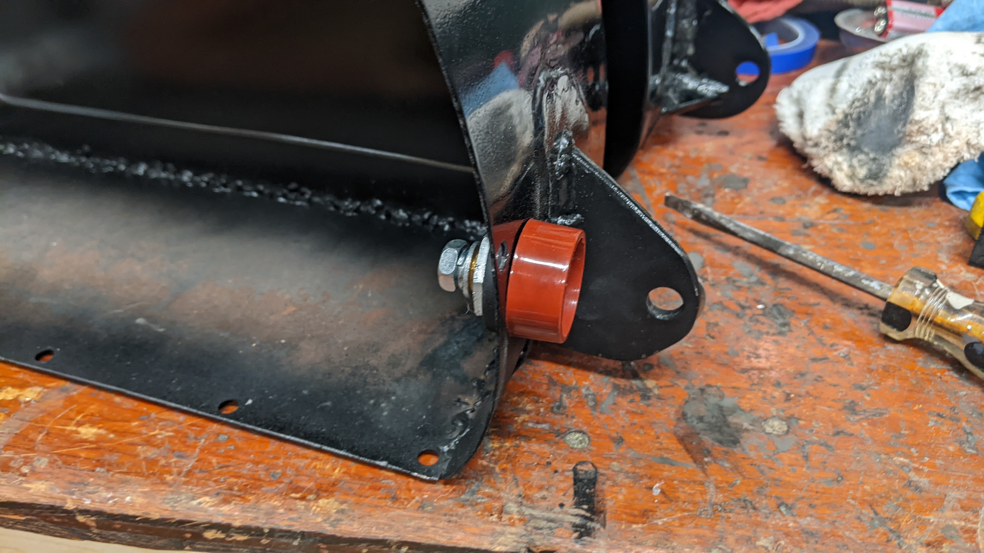
I also used the bead roller to create an overlap so that the two halves could fit together and also be water tight. And I welded in nuts, there are 17 bolts altogether, to keep it strong and to spread out the load.


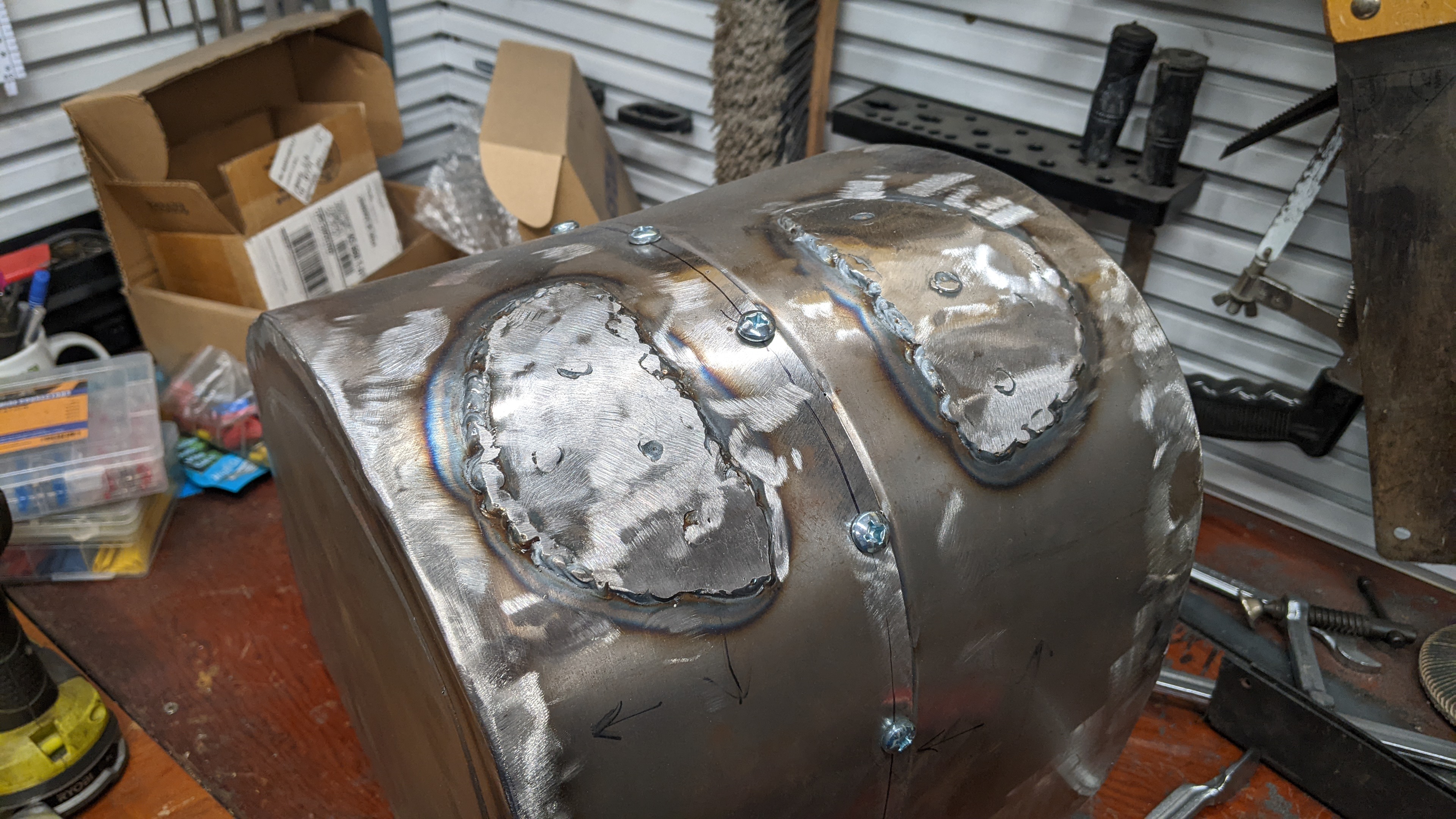
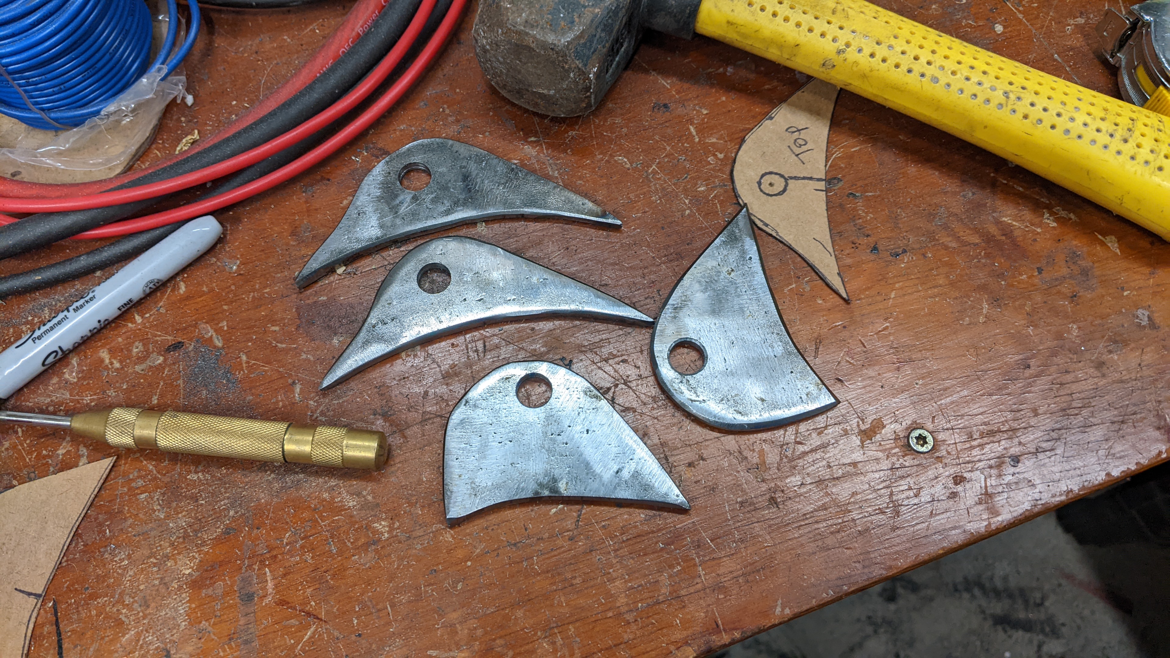
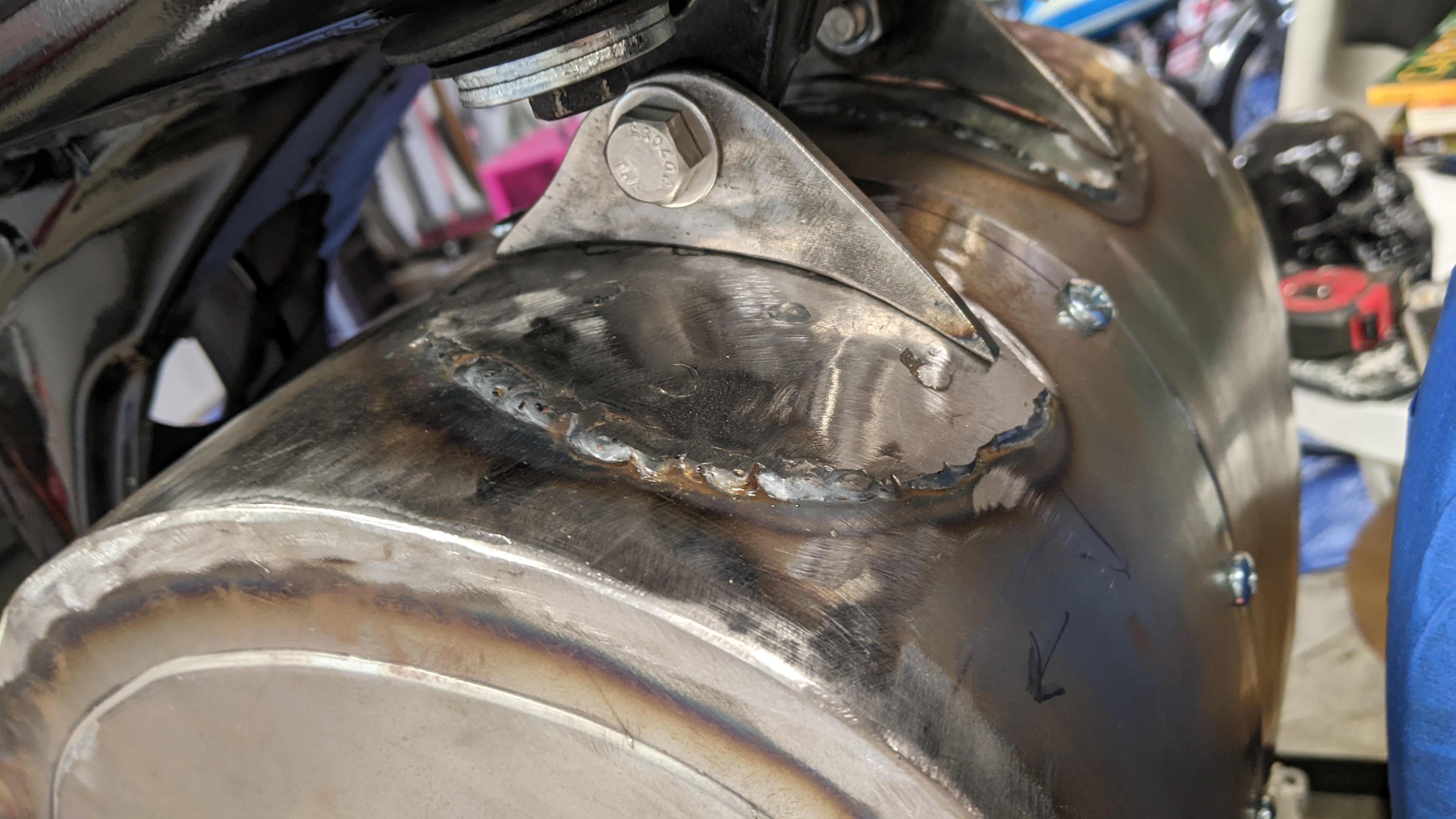
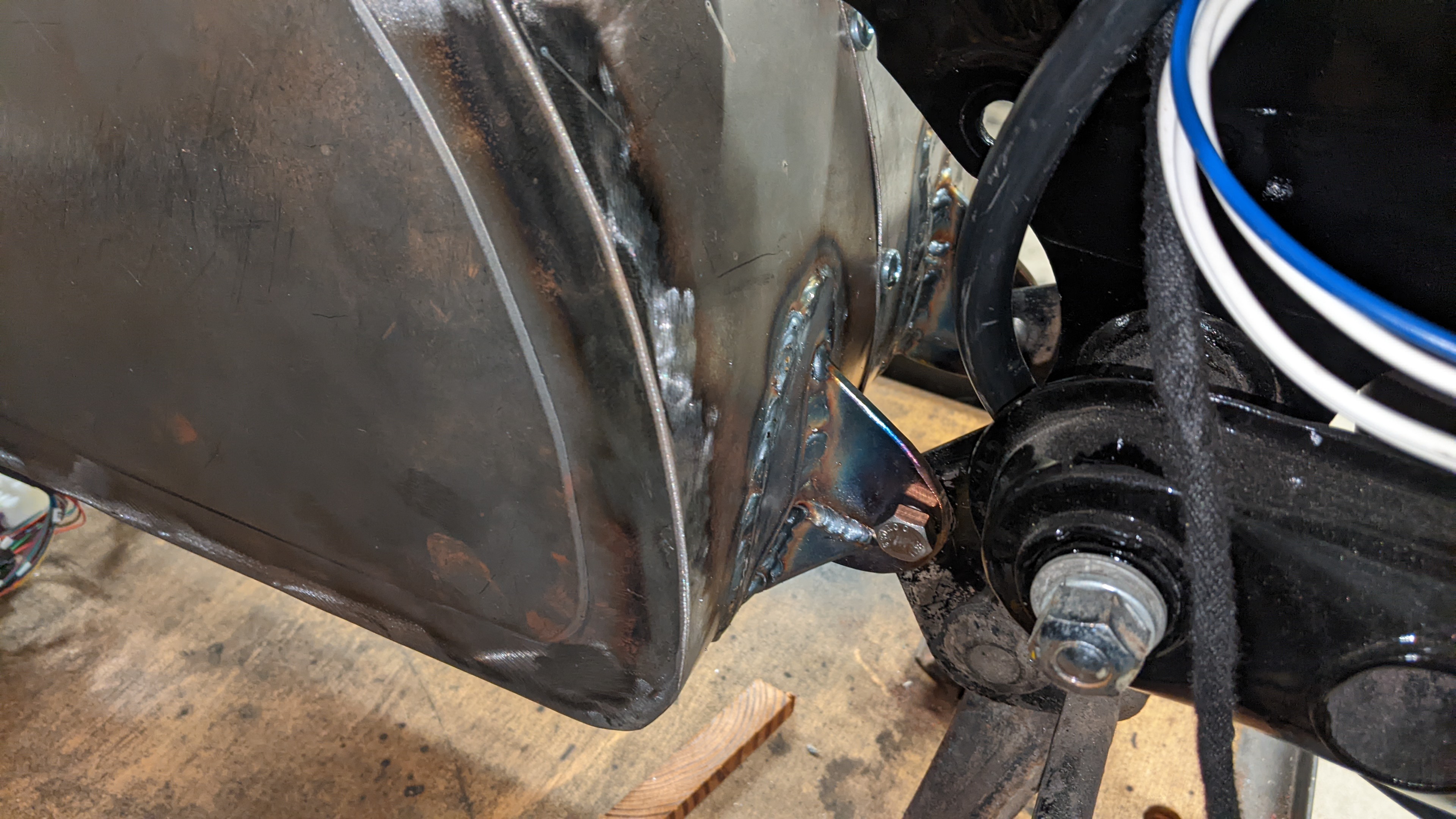
I used 18ga sheet steel, so before I welded on the brackets that would bolt to the frame, I wanted to add a little more meat for welding onto. So I made these 16ga pieces ("fish" plates?). In hind sight, it looks a little ugly, not sure what I could have done differently though.


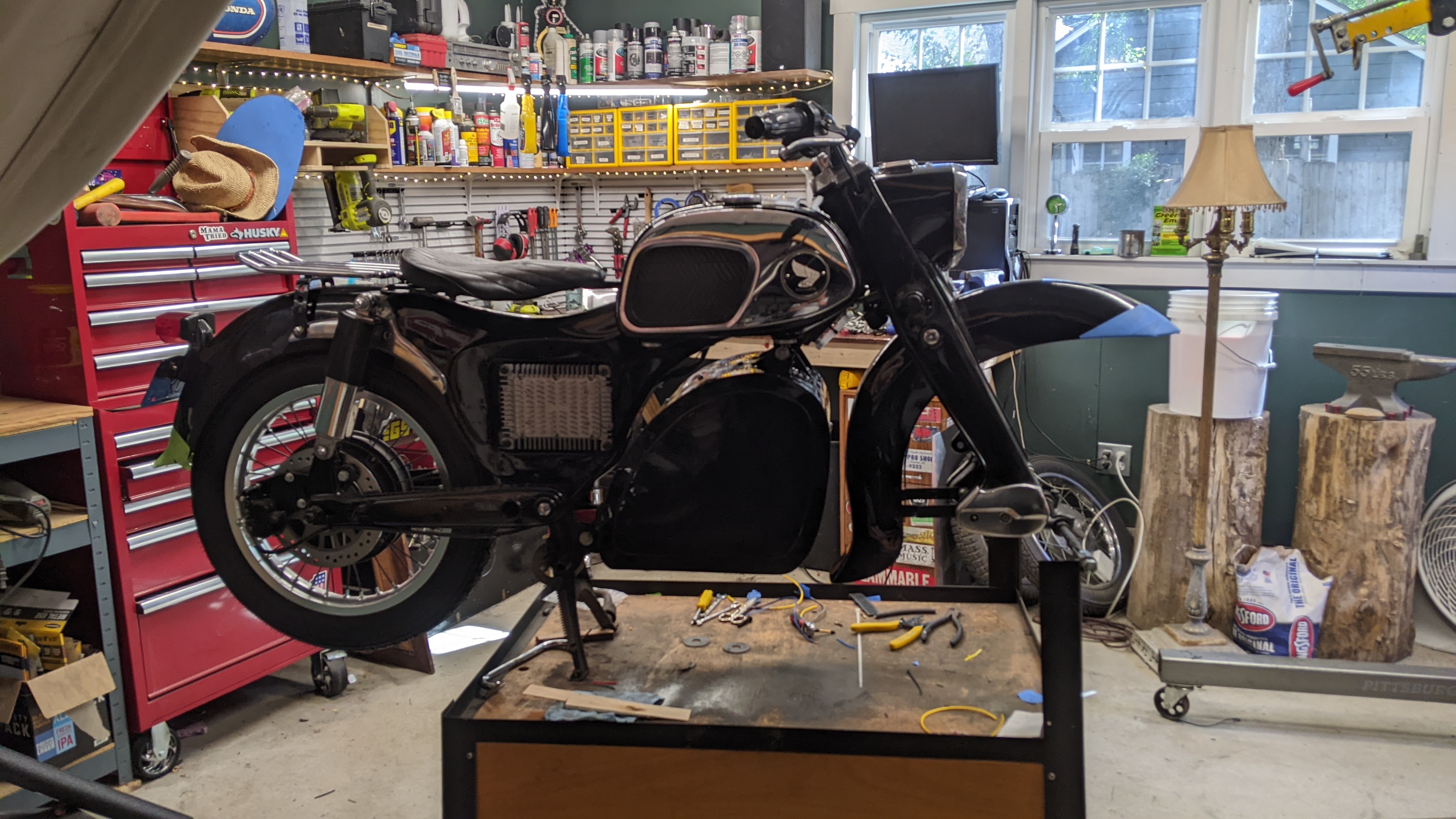
I bolted the bracket pieces to the frame, then put the metal encluse in place and where I wanted, then put a few tack welds on, then removed it and finish welded everything off the bike.


I think it looks really good and I'm very happy with it, can't wait to put on the paint! Will probably need to do a little bondo first, though. 16 days until the car show that I'm trying to get this bike ready for!
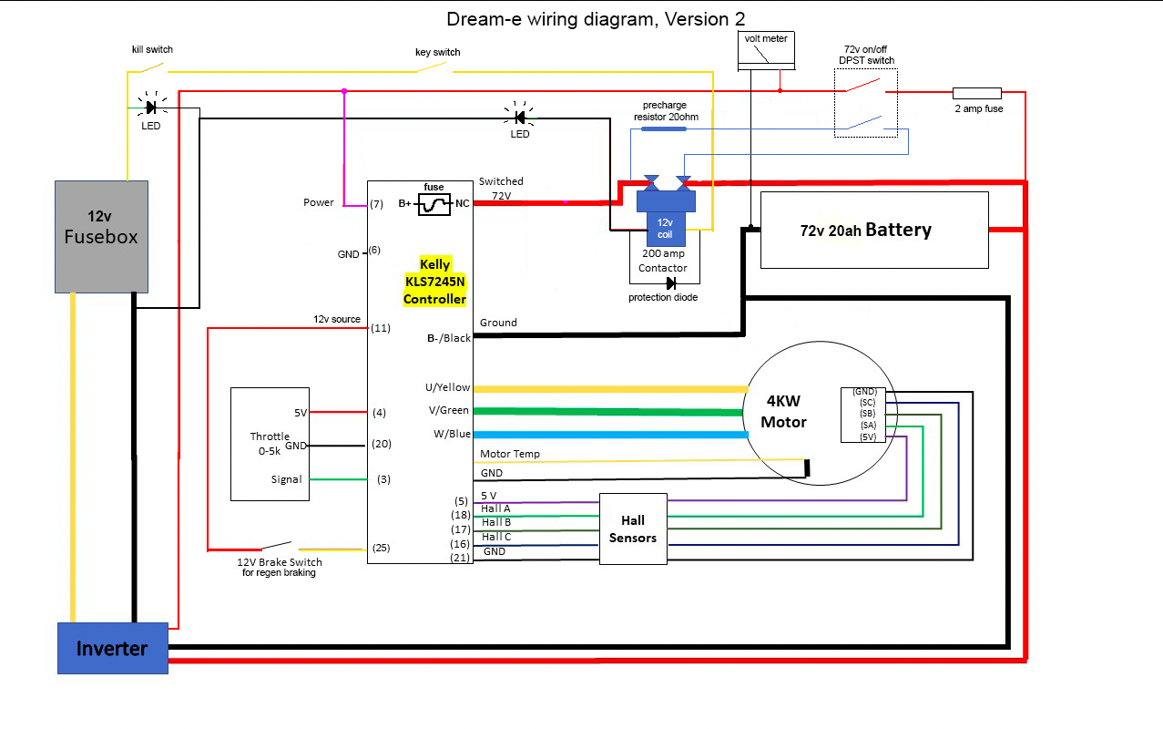
 
thisi build is insanely awesome ...everything you are doing is top notch...loooove the baby dream...thats a super fun seat...
 
I painted the battery enclure with the same paint as the bike frame, black 2-part urethane single-stage paint from Eastwood. I then wet sanded and buffed. I may add something to the enclosure's sides, such as laser cut aluminum, or decals, some silver paint, or something. But I'm not sure yet, I'm just letting the black paint do its job.


I used these "dinse" style connectors, like what you see on a TIG welding machine, to act as bulkheads for the enclosure. I haven't seen another builder use these before, but it should work pretty well. And I used this socket for the charge port. 


Here is a closeup of the connector. I slipped terminal covers over the connectors' metal bolts for added protection on the inside of the enclosure.


And here it is all bolted to the frame and looking great!


More photos coming very soon!
 
Back
Top