mannydantyla
100 W
- Joined
- Dec 4, 2020
- Messages
- 126
Time to wire everything together!!

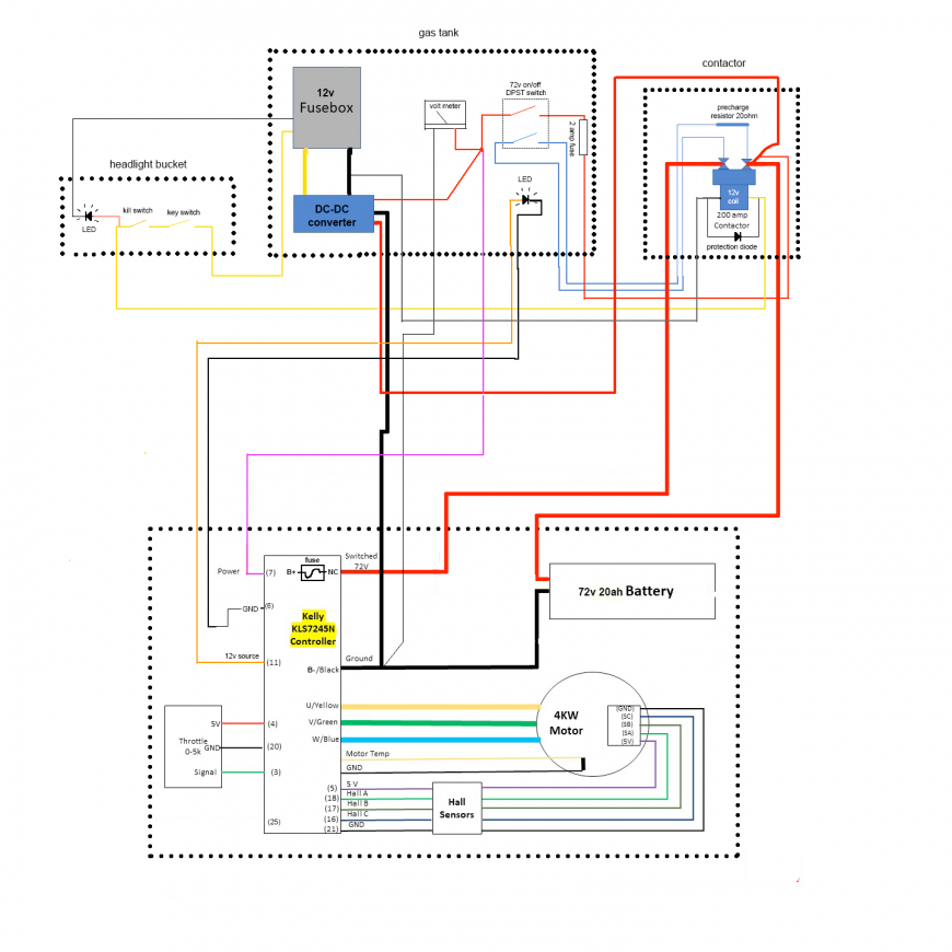
Here is my final version of the wiring diagram:

This is excluding anything that is not required to get the wheel spinning. So, no headlight, taillight, horn, etc. (I still wired up the headlight, tail light, and brake light, just didn't need to see a diagram for that. No turn signals and horn, yet.)
Then I re-arranged the diagram to organize it into the sections of the bikes where the wires would go, this helped me to visualize it while I was doing the wiring, and this is the diagram I kept open while wiring the bike:
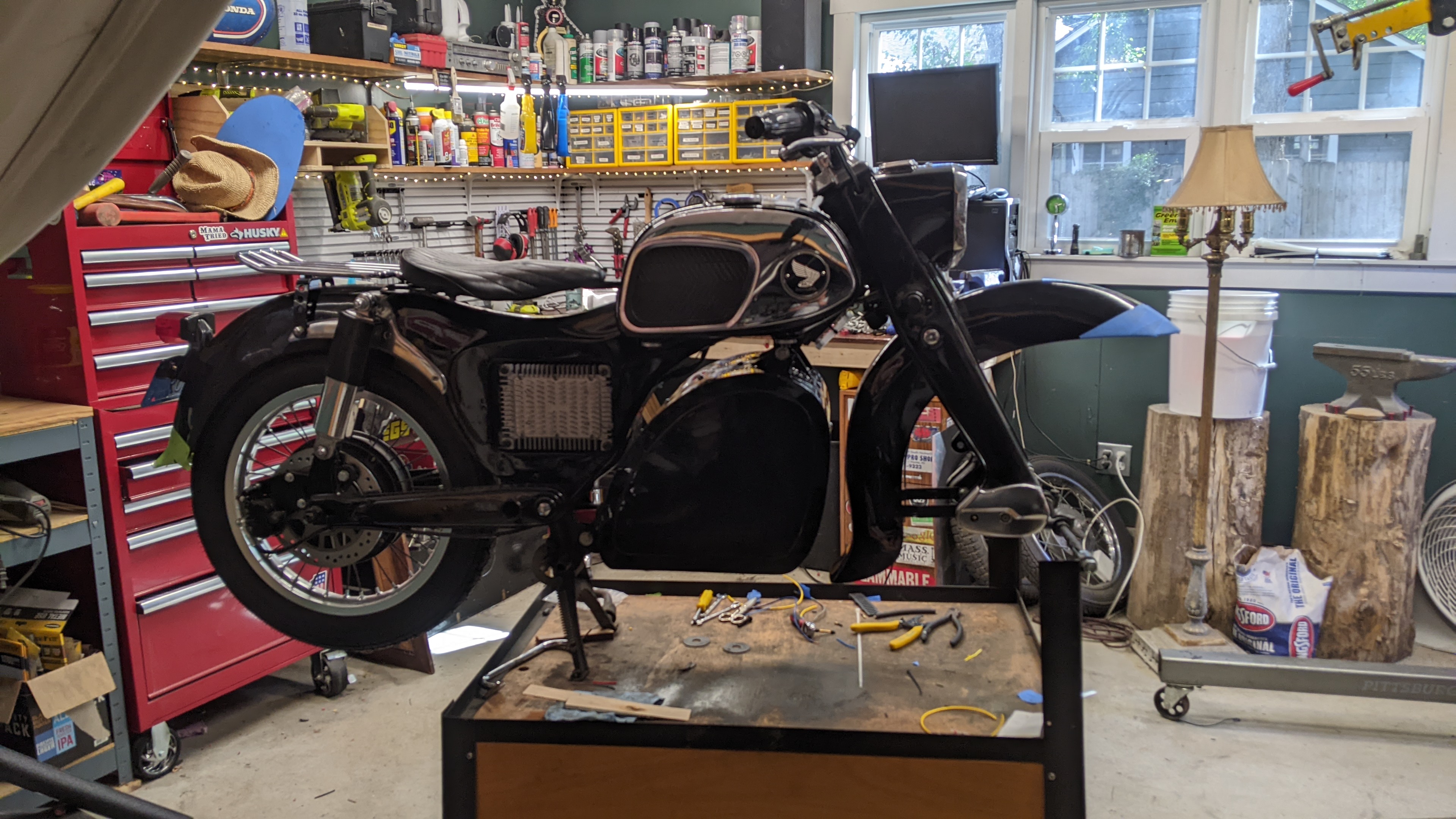
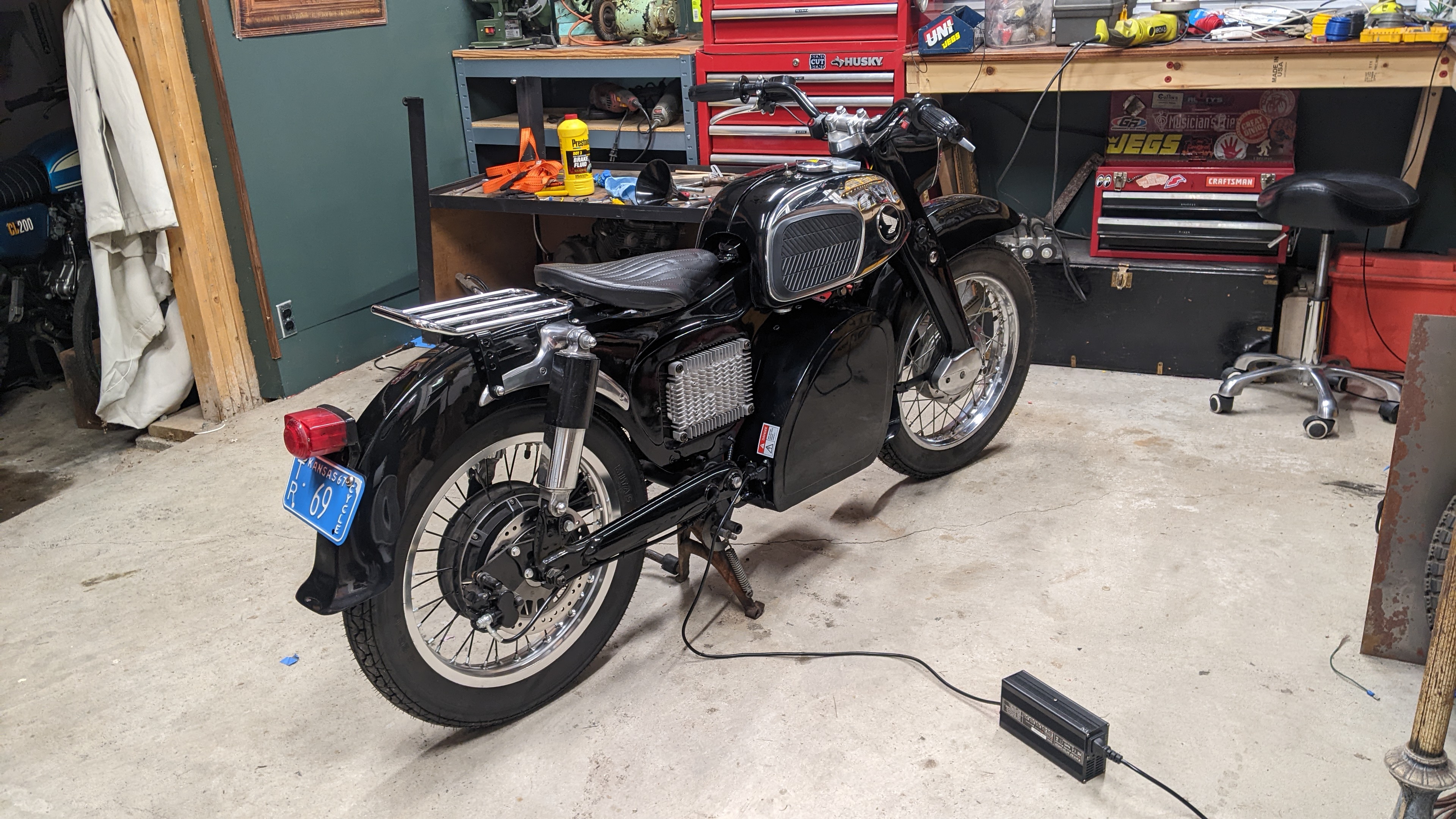
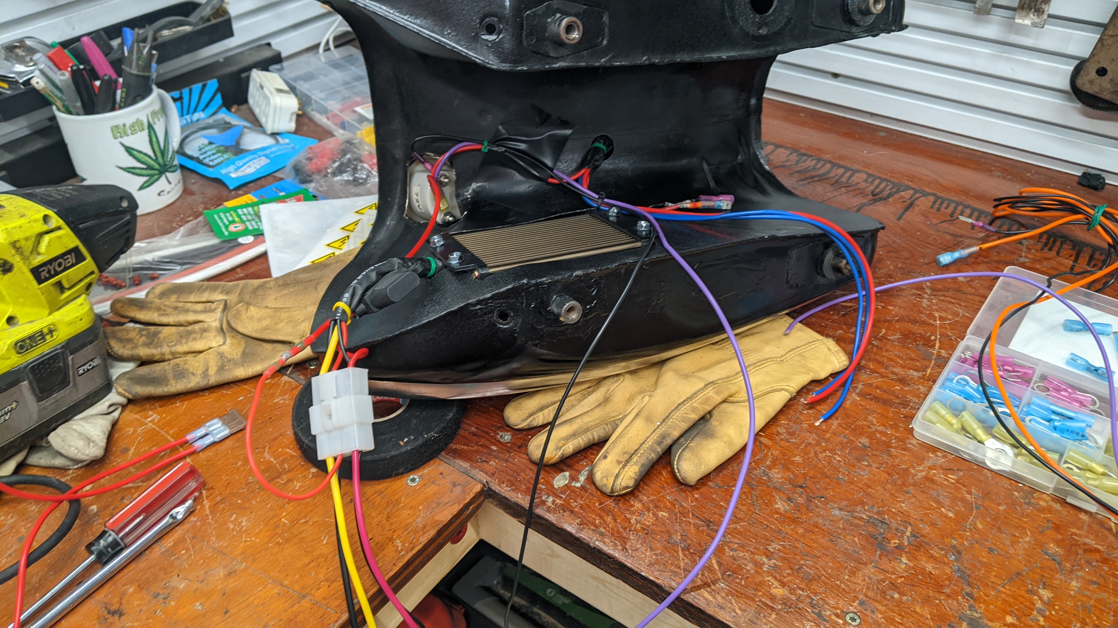
The contactor is located deep into the frame, under the seat. I connected all the wires to it before bolting it into place, and there were many of them because I used one of the large lugs as a distribution terminal for the 72v circuit.
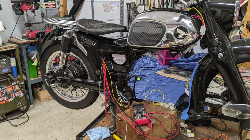
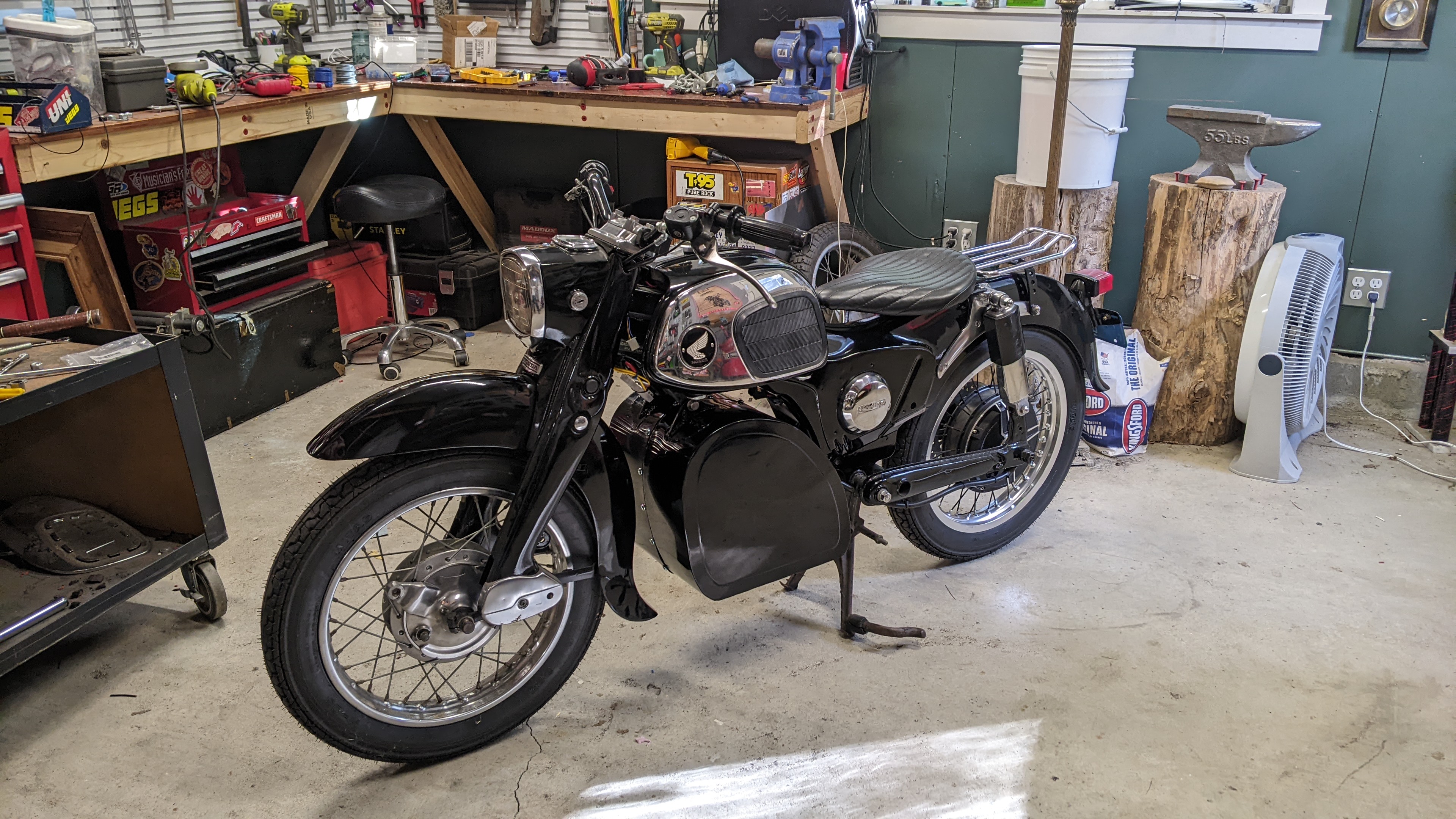
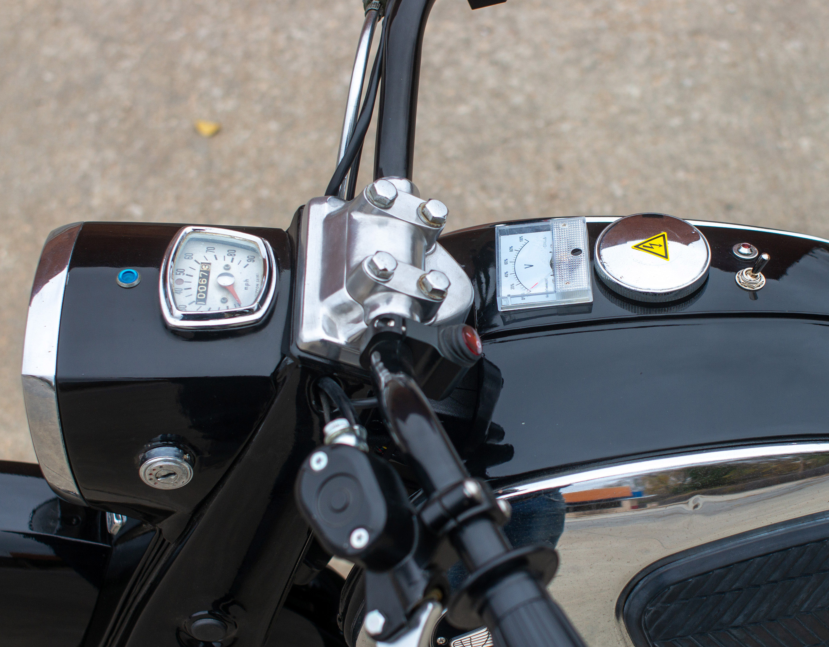
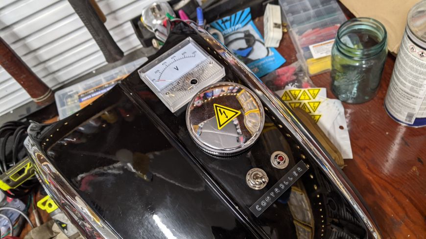
I didn't want to do this at first, but I finally accepted what had to be done. I had to cut and drill holes in the top of the gas tank for some of the components. But I must say, it does look good! (I ended up not keeping the label bellow the rocker switch and LED).

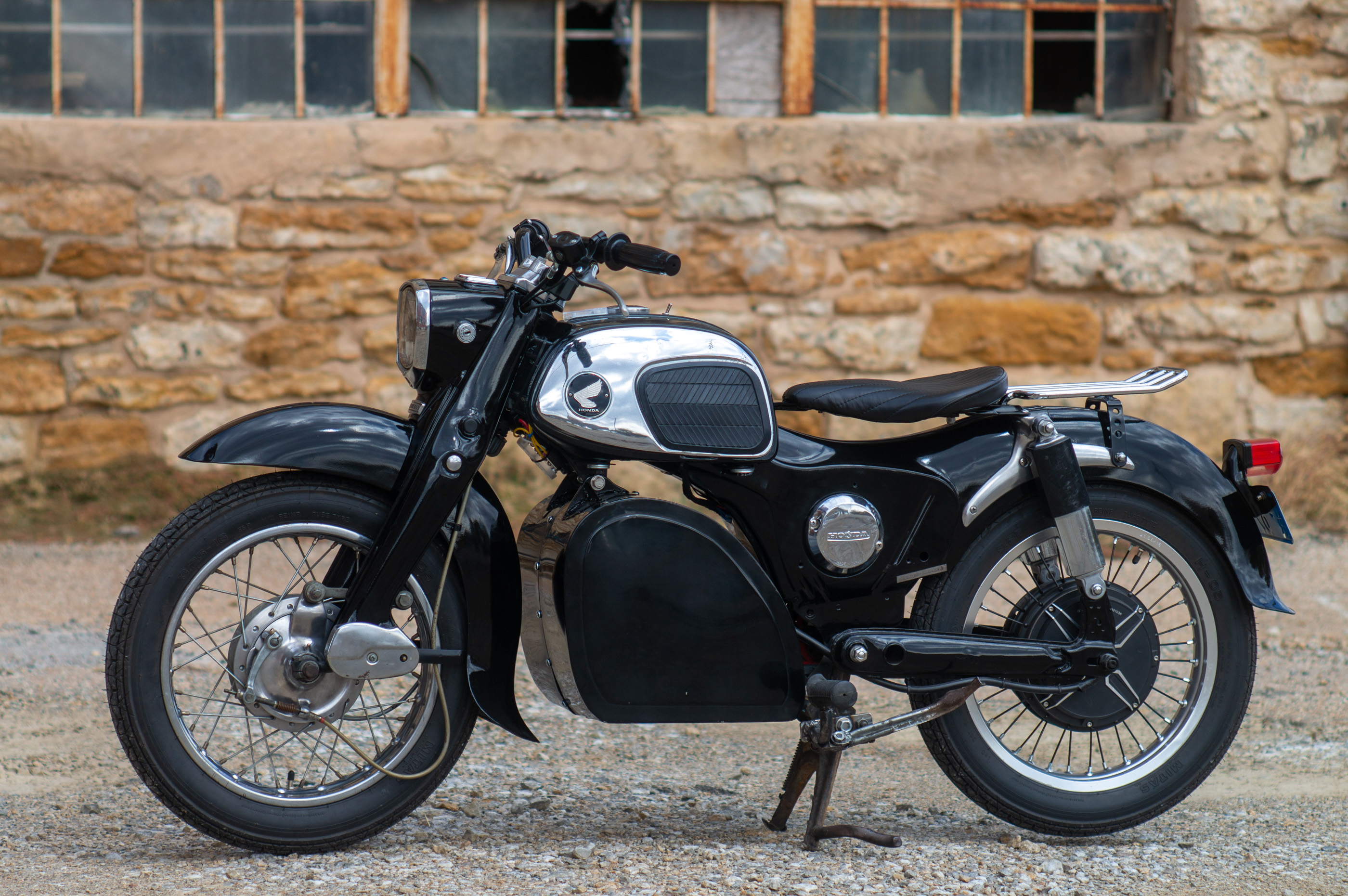
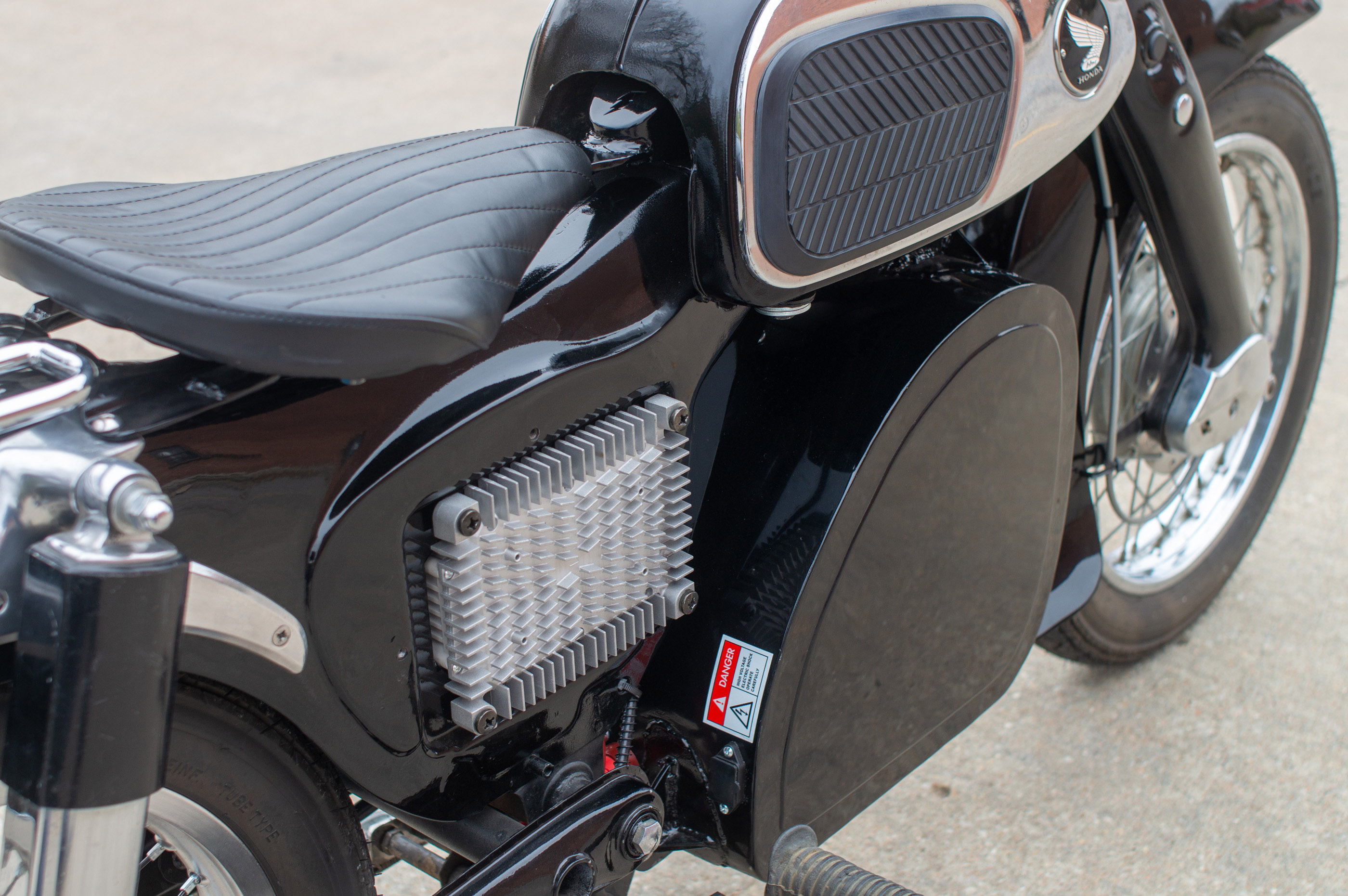
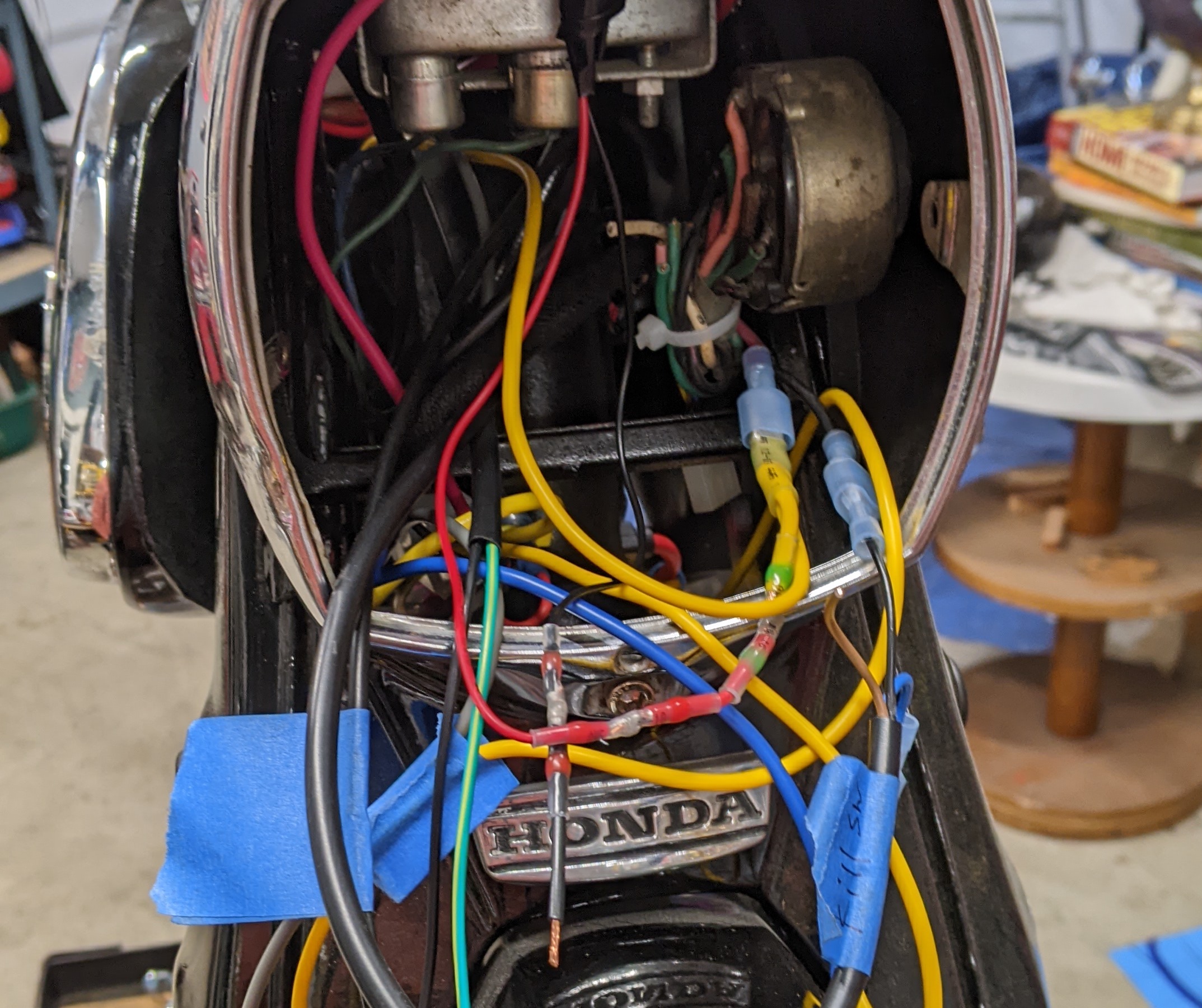
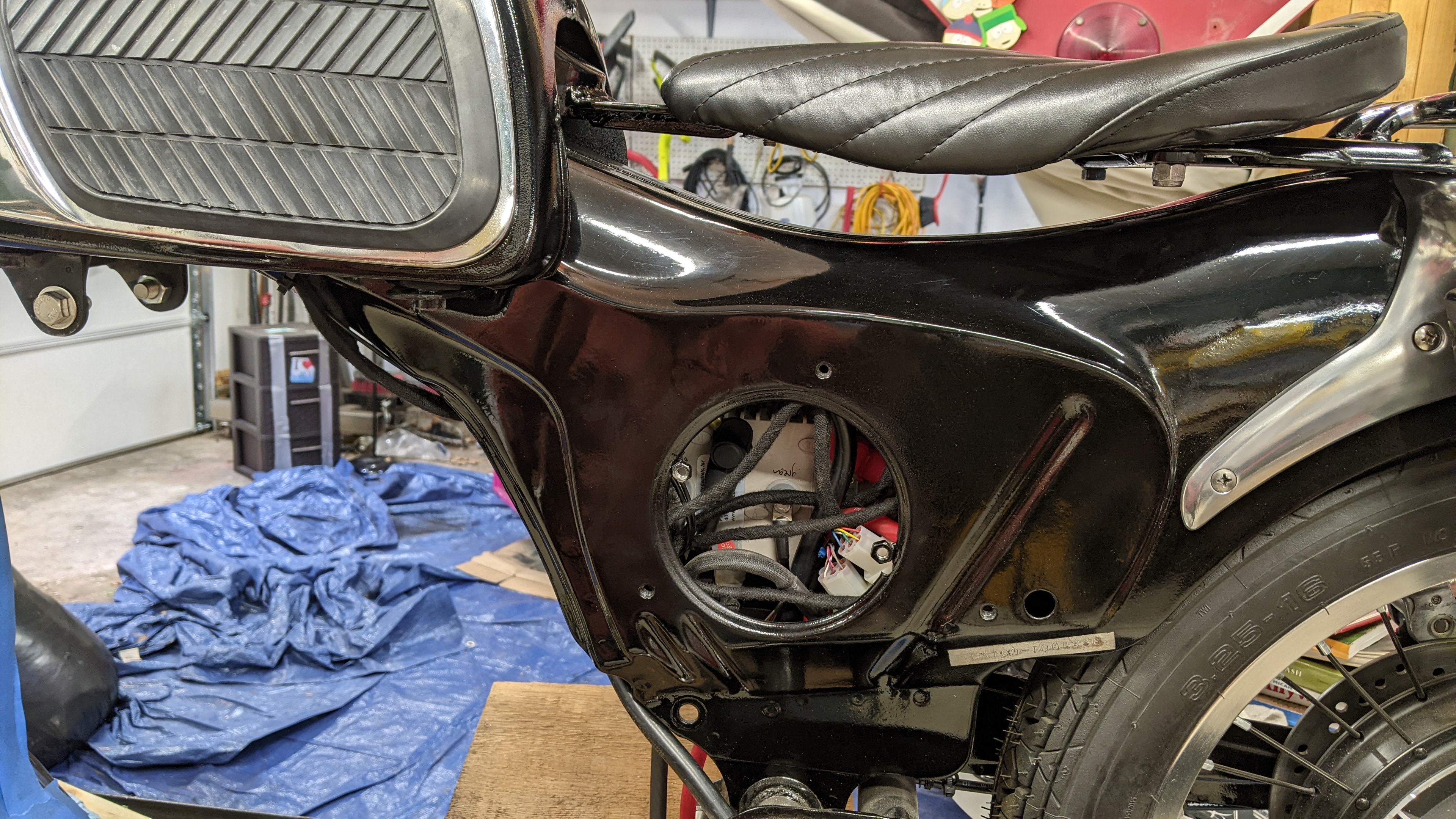
I had access to the back of the motor controller via the hole in the other side of the frame, that made it easy to access the wire lugs. I then covered the hole with a re-purposed chrome Honda clutch cover that I found in a parts bin.

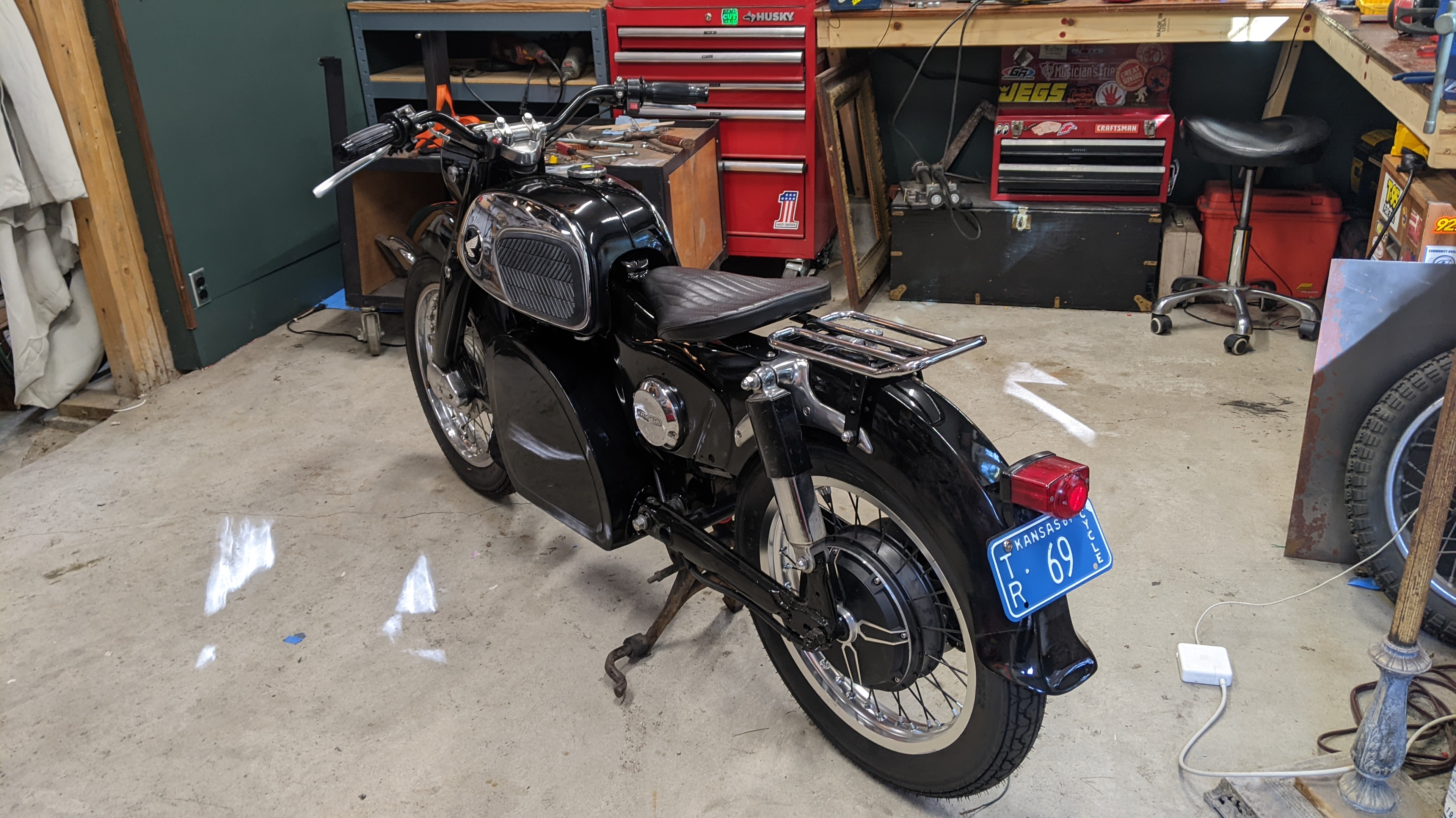
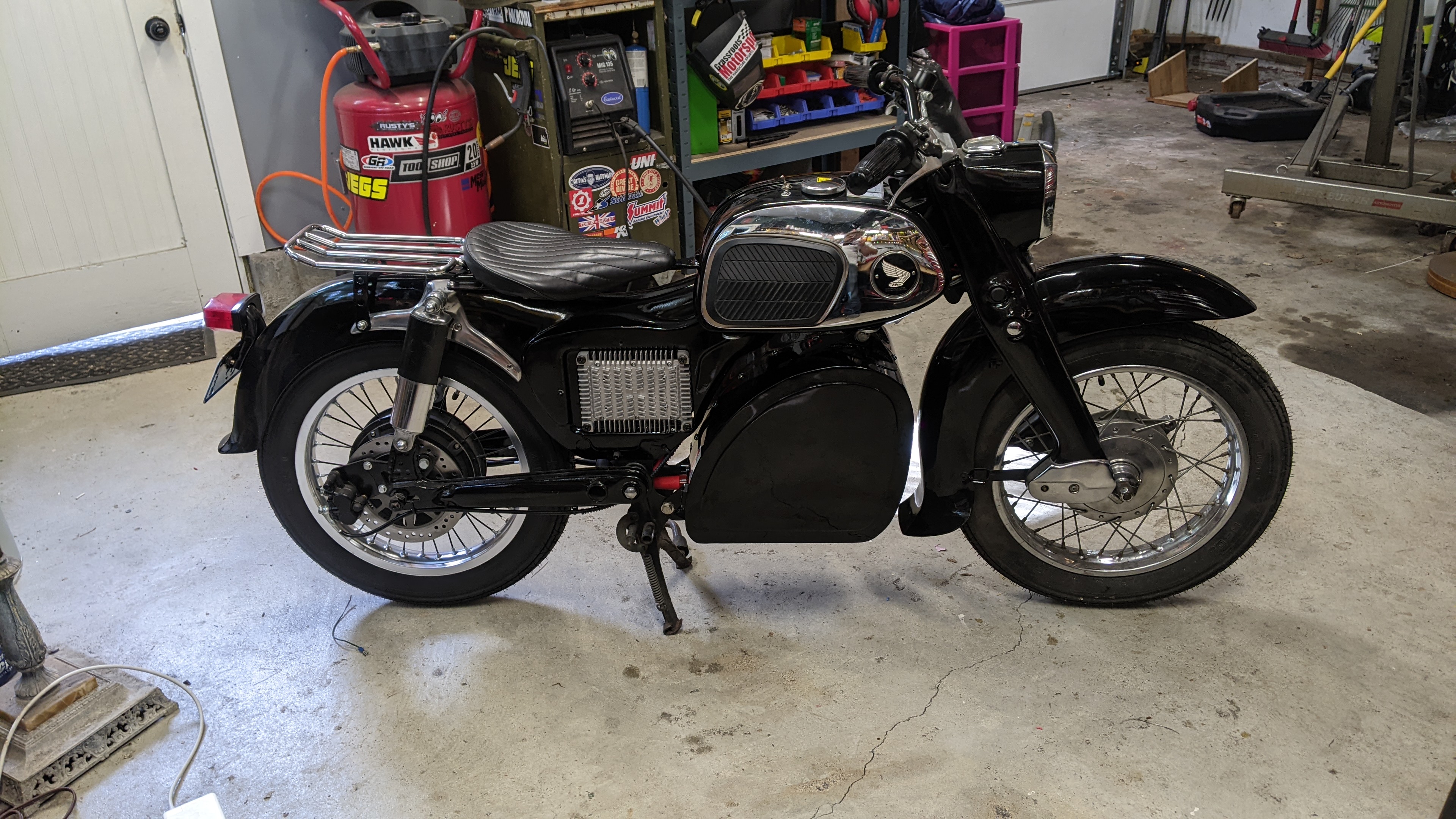
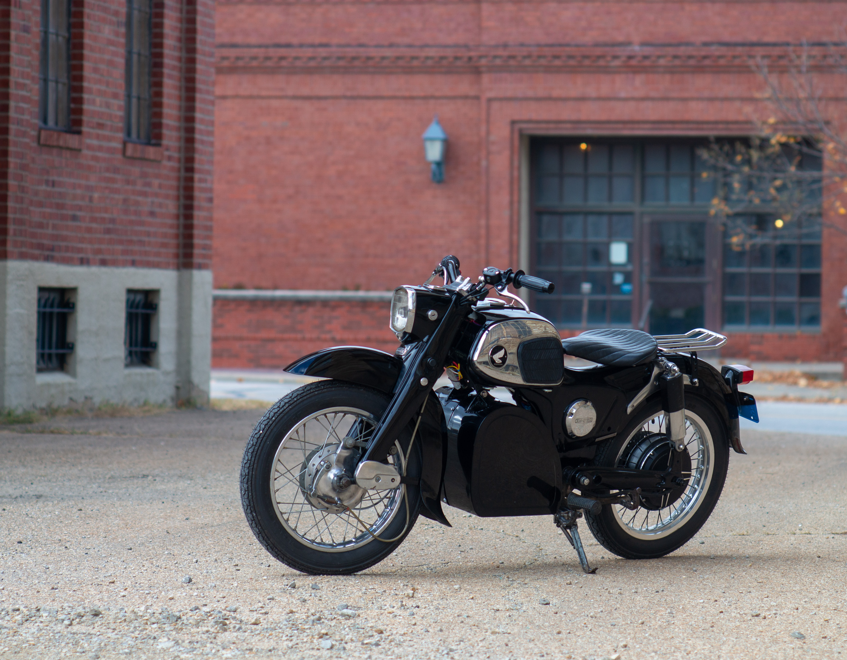
Almost done now!!

Here is my final version of the wiring diagram:
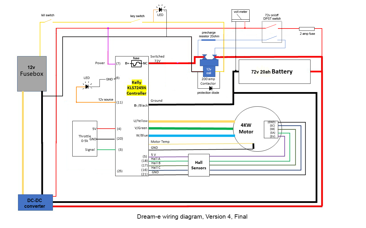
This is excluding anything that is not required to get the wheel spinning. So, no headlight, taillight, horn, etc. (I still wired up the headlight, tail light, and brake light, just didn't need to see a diagram for that. No turn signals and horn, yet.)
Then I re-arranged the diagram to organize it into the sections of the bikes where the wires would go, this helped me to visualize it while I was doing the wiring, and this is the diagram I kept open while wiring the bike:
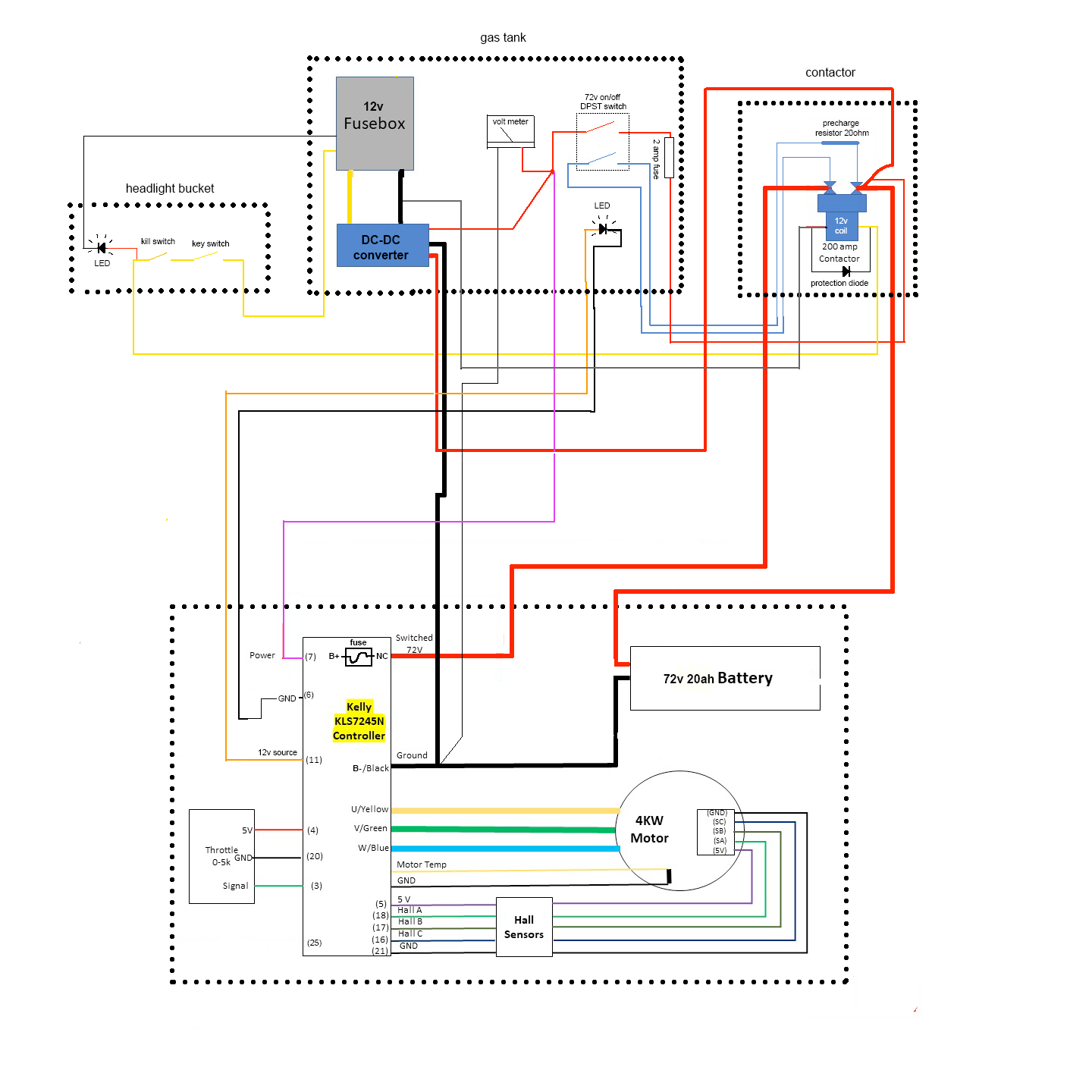
The contactor is located deep into the frame, under the seat. I connected all the wires to it before bolting it into place, and there were many of them because I used one of the large lugs as a distribution terminal for the 72v circuit.

I didn't want to do this at first, but I finally accepted what had to be done. I had to cut and drill holes in the top of the gas tank for some of the components. But I must say, it does look good! (I ended up not keeping the label bellow the rocker switch and LED).

I had access to the back of the motor controller via the hole in the other side of the frame, that made it easy to access the wire lugs. I then covered the hole with a re-purposed chrome Honda clutch cover that I found in a parts bin.
Almost done now!!