N.E.S.E. the no solder module

There is one thing i would like to get your thoughts on. After nickel plating, copper gets tempered and brittle. When tabs are bent in the module you can hear cracking sound and it feels like it will snap of after couple times. I have tried annealing with heat, simply heating it up with torch and it made it soft again although still cracking, felt like it would hold a lot more bends before needing to anneal again. My question would be if i should leave it like that and people who intend to reuse it, do the same with annealing just that spot or should i anneal whole tabs?
I don't want to make the whole tab soft and to manually do each tab with the torch would be nightmare.
On the other hand people might be put off by this additional step in the process.
 
people will be put off by an additional step, however, they will also put off, if they feel the tab is cracking
 
Bravo Agnesium !

Your design looks really professional and I love the fact that it's using nickel-plated copper too (the best conductor to use IMHO) !
I think 3D printing is awsome for small scale production.
I'd wonder if this is too complicated to create a cast mold from the 3D-printed parts so we could inject the mold with acryl monomer and polymerise to polyacrylate (plexiglass) or polycarbonate (most sturdy clear plastic). Making it kevlar would be incredibly strong but I dunno if it's possible to inject into a mold.

The PTFE used in your printer is polytetrafluoroethylene (aka teflon) which is another polymer of monomeric (tertrafluoroethylene) F2C=CF2. The polymerisation reaction is by free redical propagation mechanism. PTFE certainly has very interesting electrical isolation properties! I think it's a good choice of material.
Nice one !

Matador
 
Not an expert here. I did artisanal nickel electroplating on copper. I've noticed the lower the current I use i the plating, the better the result. Fast plating at higher current yielded plating that would flake off. Low current (relative to surface area of plating) and higher distance between anode and cathode yielded a much better clean looking plating. Of course, I wet sanded each part by hand before plating which is extremely labor intense, but skinping the plating and leaving behind resides like finger oils would spoil the whole plating procedure.

Nevertheless, nickel will make copper much more brittle and a lot harder, as nickel it is less flexible than copper. The plating really does not need to be much thicker that 5 or 10 microns to confer oxidation protection. So thinner is best IMHO as the is less chance of cracking if bent IMHO.
 
Could you maybe use brass rather then copper? Brass is solid as a rock and got "close to" the wanted properties of copper. There are brass alloys that are close to 60% of copper codnuctivity.

I think you could go thicker with brass to compensate for the lesser conductivity. Brass you could bend without it being brittle. Also look up cr brass.

Or just go all in and use gold plated silver ;)
 
I have not seen brass being 60% conductive anywhere. That conductivity is for aluminium while brass is more in 40% region. I don't like the idea going thicker. Thinner copper adapts and gives where needed when pressure is applied.
Another option would be to leave terminal area unplayed.
 
Yeah I pulled that from old mans memory, could be I was wrong but there are various versions of brass. Some with more copper and less nickel and those are the ones best suited for conductivity. I think you will need to check with a metal specialist to see what type of brass would be the best. I would not rule out brass without checking with a specialist.

If you double the thickness of the brass as opposed to the copper you should be spot on. You will loose in the weight department a little to thinner copper sheets, but you will gain in strength, durability and ability to withstand corrosion.
 
agniusm said:
I have not seen brass being 60% conductive anywhere. That conductivity is for aluminium while brass is more in 40% region. I don't like the idea going thicker. Thinner copper adapts and gives where needed when pressure is applied.
Another option would be to leave terminal area unplayed.

I have played around with tin copper braid. Very flexible and conductive...
 
I haven't given up on the idea of nickel-plated copper for the busses, but I did see copper ribbon purchasable for the solar-PV panel installation mechanics. It appeared to be copper ribbon on a roll, but it had been dipped with a thin layer of solder previous to rolling. It made connecting the various parts in the field easier for a tech who didn't have three hands, and it was also for weather corrosion protection. just a thought...googled some terms

Tinned copper flat wire
Solar Bus Wire

I'm not suggesting this product is an option for battery pack busses, I'm just saying that using lead/tin solder as an anti-corrosion anti-oxidation coating is a widely accepted practice.
 
Special thanks for your devotion Agniusm...

You are the TESLA of eBikes... :)

Here is a company in USA providing all kind of copper attachements for electrical purpose...
It might give you some idea...
https://stormpowercomponents.com/
 
Bison_69 said:
Special thanks for your devotion Agniusm...

You are the TESLA of eBikes... :)

Here is a company in USA providing all kind of copper attachements for electrical purpose...
It might give you some idea...
https://stormpowercomponents.com/

Thank you but you are over exaggerated. I am just refining something that came up on ES.
Thank you for the link, i will look into it.

I guess tin coating is my next thought. Nissan leaf bus bars are all tin coated, many ring terminals are also tin coated so it must be a better option?!
 
I just broke one tab on a single bend. It is so brittle after nickel plating that i don't know what to think. It was ok on the previous design as there were no bends to be made but here it just wont do. Will do tin plating to see how better it is.
 
contacted plating company who specializes in tin plating. Looks like it is the way to go. they have big orders for german electrical company and all bus bars and conections are tin plated. Its a cold process so it is the way to go. waiting for first 100 mudules batch for testers to arrive and will do tin plating asap
 
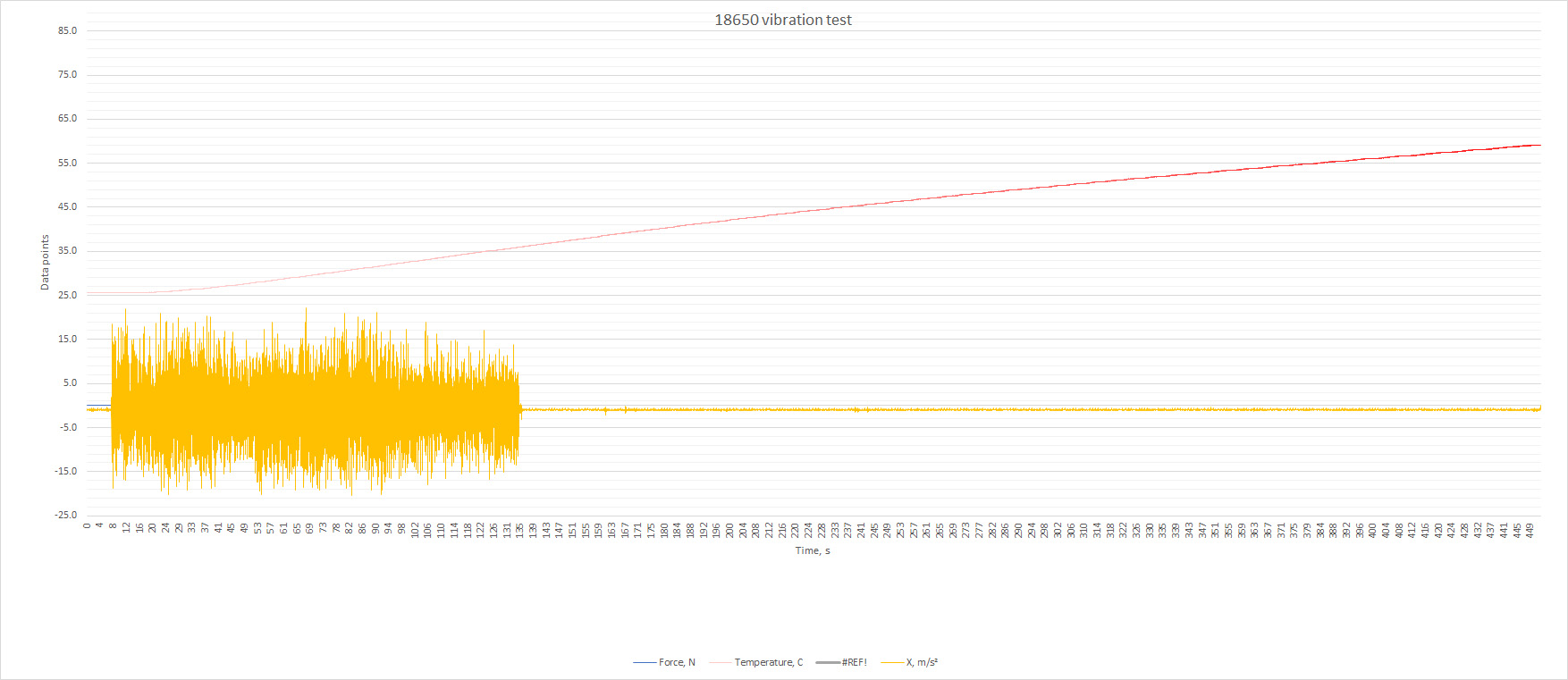
Just did a test on the module. Welded some stainless wire to stainless flat bar, was going for 120A but got around 80A constant. It held good, cells went to 60C realm. Too bad my pressure sensor got ripped. My video is still rendering and will be available later but here is collected temperature data:

SAtAfcF.jpg


[youtube]qmdiBf__BYU[/youtube]


I am really impressed how these modules held up. The cells are rated 20A max so they held pretty good as well, althou i wish it was 120A :) Will weld some more wire and see if i can bump it up.

Anyway, it is visual confirmation that my spec'ed 50A nominal is not vaporware ;)

P.S. note i disconnected my shaker, cause could not get proper reading of temp and it was riding across the room like mad and i could not move camera to point to different bits.

I hope this thread will be moved to battery section where it belongs.
 
Would there be any issue with doing something like purchasing the "5P" holders and only putting 4 cells in each one?
That way if I decide that I actually need a longer range pack for most of my rides, I could just add the extra cell to make it a "5P" pack...

Thanks,
Leelorr
 
62°C is to be expected after pulling 19A-->13A per cell for a full discharge cycle (or close that at least.... That 2.90V bounces back to 3.45-3.50V once at no-load and after hysteresis effect sets back for few minutes). I see around 40 to 45 millohm DC internal resistance per cell (the wires are awesomly big... so their resistance is probably neglectable). Well I guess your 50A rating is conservative for the module ! You modules bussbars (nickel plated copper) seem like great job... not adding much resistance, especially for a soderless kit!! Just bend the bussbars before nickel-plating hem so they wont be too brittle and break. They're definitly worth having rather than other metals around. Top notch! What cells are in ??

I wonder grossly how much that would come up to, let's say I'd wanna make a 14S12P (28 6P modules).
 
Thanks. You can't bend them before hand. They need to be inserted strait and then bent. I think tin will do just fine, in the end I take function over aesthetics.
I need to get the pricing sorted and different bits coming from different places are a bit time consuming to calculate.
On the site first purchase will have to include a digital product, which is my module 3d designs, that's a contribution towards the greater cause:) then sets of tabs, bus bars and hardware will be unlocked so you could purchase as many as you need. Until they arrive you have time to find a local chap for you to print enclosures and then some half hour to assemble.

P.S. I use LG HE2 2500mah 20A cells but I will get 6 Sony vtc5A to push it further and see where it caps.
 
Wow. I played it in slow motion...

From start, fresh of the charger, voltage drops from 4.134V to 3.440 V while drawing 113.9 A at the moment you close the contact.

INITIAL (100% SOC) :
Voltage drop (dV) = 0.694 V
Current load (I) = 113.9 A
So R = 0.694 V / 113.9 A = 6.093 mOhm DC (for a 6P pack of ??? HE2 ??? cells with all conductive parts)
Heat lost from that resistance : dP = dV x I = 0.694V x 113.9A = 79.0 Watts (for whole pack)... The remaining 391.8W go straight into the load (nichrome or motor).
Considering your pulling an incredible 470.8 Watts from JUST 6 CELLS, the heat loss are VERY MINIMAL.

This goes to show you battery holders and conductive parts are really high quality and low resistance.

6.093 mOhm for 6 cells (+ conductive parts) is equivalent to having 36.6 mOhm DC internal resistance PER CELLS !!!!
If your cells are HE cells, there probaly rated around 30 milliOhms DC (or mayber araound 15 to 20 mOhm AC 1kHz impedance), I dunno,
But it's as if your solderless kit and it's conductive parts were all resistance-less and it's only the internal resistance of the cells themselves that account for the resistance of the whole system.

I'm honestly impressed. Don't think I could have done better even if I had the equipement and time for the R&D. Bravo!


FINAL (Almost 0% SOC) :
Voltage drop (dV) = 3.359 V (still some hysteresis would probably go up to 3.50 after five minutes rest) - 2.892 = 0.467 V
Current load (I) = 75.9 A
So R = 0.467 V / 75.9 A = 6.152 mOhm DC (for a 6P pack of ??? HE2 ??? cells with all conductive parts)
Heat lost from that resistance : dP = dV x I = 0.467V x 75.9A = 35.4 Watts (for whole pack)... The remaining 254.9 W go straight into the load (nichrome or motor).

6.152 mOhm for 6 cells (+ conductive parts) is equivalent to having 36.9 mOhm DC internal resistance PER CELLS !!!!

Anybody tried to measure the DC internal resistance of these cells HE in the past (im not talking about AC impedance here).... I mean mesuring precise voltage drop and amp load with beefy 00 connectors to each poles of one single cell...
If we know, we'd able to precisely quantify just how low the resistance orf the NESE kit is... The future looks bright !

Matador
 
Wow, I could not ask for a better feedback on test results. That was quick and so detailed, I was waiting for such opinion on my initial design, 14S6P.
Thanks mate for kind techie words.

Here is a link on the cell I used and they are the ones I purchased from, legit brand cells:
https://eu.nkon.nl/rechargeable/18650-size/lg-18650he2-imr-battery.html

PDF says AC ir at 1khz is less or equal to 20mohm's
 
agniusm said:
Wow, I could not ask for a better feedback on test results. That was quick and so detailed, I was waiting for such opinion on my initial design, 14S6P.
Thanks mate for kind techie words.

Here is a link on the cell I used and they are the ones I purchased from, legit brand cells:
https://eu.nkon.nl/rechargeable/18650-size/lg-18650he2-imr-battery.html

PDF says AC ir at 1khz is less or equal to 20mohm's


You're welcome.
Yes mostly give values in AC internal impedance rather than DC internal resistance. Easier for them since it doesnt vary as much with SOC. But for us, DCIR is much more usefull to get a grasp at potential voltage drop, current rating and heat losses.

I found a graph of the HE2.
I modified it to extrapolate values. Assuming graph is okay, and that your voltage reading are close enough to cells post, we can use it to calculate DCIR of cell and substract it to pack resistance to get the resistance of connector in NESE kit.

So INITIALLY you had : 3.440V@113.9A, which is 3.440V@18.98A per cell (since it's a 6P pack, right)
FINALLY it finished at : 2.892@75.9A, which is 2.892V@12.65A per cell.

I placed these values on this graph to extrapolate values : LG HE2 (Matadors calculations for Agnesium).jpg
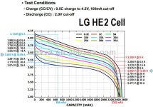
From these, made calculations in Excel :
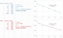
Taking Agnesium's Load range into consideration (between 0 and 20A):DCIR1 LG HE2 (Matador).jpg
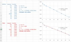
Taking All possible Load range into consideration (between 0 and 35A):DCIR2 LG HE2 (Matador).jpg

So it seems that when you start the experiment at 75% SOC a LG HE2 cell should be around 23.4 mOhms_DC internal resistance. And when you finish the experiment at around 8% SOC, it should be at around 18.7 mOhms_DC internal resistance.
That is, if we assume the graph is correct, and if your voltage readings see neglectable voltage drop from wiring lenght (as if voltage readings were taken directly on battery cells posts.... still, I'm not worried about that as the cable you use look massive gauge).

So theortically, if we put 6 cells in parrallel (1/R = 1/R1 + 1/R2 + ... + 1/R6), then we get resistance of 3.9 mOhm (initally) for 6P pack and 3.1 mOhm (finally).
In practice, your pack has grossly (very crude estimate since I use one of the voltage values which is a no-load value for DCIR of pack calculations) 6.1 mOhm (between 6.1 and 6.15 mOhm).

So connectors add up just like resitors in series add up. So your connectors (2 bussbars, 2 bolts.... and neglectable resistance value of the crazy heavy gauge wire you use) in NESE kit are adding in total R = 6.1 mOhm - 3.9 = 2.2 mOhm (initially)
or R = 6.1 mOhm - 3.1 mOhm = 3.0 mOhm finally (conductors a bit high temps ?).

So a 6P NESE module adds only between 2.2 and 3.0 mOhm resistance to the resitance of the cells in parallel...
Awesome.
If I make a 14S6P pack out of these. Total pack will be 85 mOhm, and the 6P-NESE modules will acount for 31 to 42 mOhm of these 85 mOhm.
I think this is totally unforseen in solderless technology.
Even if you use supraconductors as bussbars, there will still alway be a bit of resistance due to cell not being physically welded to bussbar but rather pressed against them.

I would try slightly wetsanding my cell's contact post with 2000 grit sandpaper just to permit better cohesion between cells pressed onto bussbars. I think it would lower total resistance even more...

Again. BRAVO!

Matador.
Oh here's my DCIR calculation Excel File :View attachment DCIR calc (matador).xlsx
 
PS, for even better resistance estimation.
Mesure voltage directly at cell posts, with short and very thick leads. Use that high quality (5 digits) multimeter and film voltmeter at the same time as ammeter.

I have a feeling the HE2 cells are even higher that 18.7 to 23.4 mOhm... Usually DCIR is around 1.5 times higher than ACIR.
and LG HE2 are stated to be 20 mOhm AI IR....

That could mean the NESE would have even less resistance from connections (but slightly more that 18.7-23.4 mOhm from the HE cells).

Also, Agnesium : are your HE cells Old and aged or fleshly manufactured and never used ?

Anyway, I wanted to show you the mathematical logical I use to see resistance values of a solderless kit. All this theoretical calculations are valid.... when performed in controlled and reproducible environnement.
I didn't make the discharge graph myself, I just extrapolated from it, which is far from perfect IMHO (did they use new cells, were the wires they used short or long, was there multimeter accurate, was it a the same temperature than in Agnesium's house that day, etc. etc..)

Matador.
 
Back
Top