Need help to wire up 24S BMS

Ypedal

Moderator
Staff member
Joined
Dec 27, 2006
Messages
12,530
Location
Moncton NB, Canada
Ok.. first of all.. me and electronics tolerate each other but damn.. there ain't no love. :oops:

In true bmsbattery fashion, what they ship is not the same as pictured on their site.. and i will be emailing them but the whole 12 hr difference thing and i want to get started on this as soon as possible... so here goes.

This is for a 24 cell Headway pack ( 15ah cells ) .. 72v

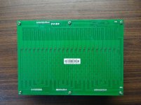
First up, there are 3 balance wire segments.. 1x 9 pin.. and 2x 8 pin ... they included the chopped off section of the 9 pin made from an 11 pin connector.. i assume this is to be discarded . ?
BMSB1.jpg

I have need to wire

- Charger
- Controller
- Battery
- Balance wires

BMSB2.jpg

On their site, the board layout is slightly different :
https://bmsbattery.com/ebike-battery/378-24s-lifepo4-bms-battery-management-system-battery.html

And there is a note " Please connect B+ to batteyr pack + directly. Please don't connect B+ via BMS board. "


So.. question no.1 : 24 cells... 25 balance wires in those three pigtails.. but a note not to use the B+ ? wtf?

No.2 : Top left corner " B-2/B-2 " .... ?

....

B+ and B- are obvious.. no problem there.

P- between the 6 hole and 4 hole stop i'm not too clear on.. all the same pad ? ... P- to controller Neg .. but what about the charger ?

Heeeelllp ....
 
Ypedal said:
Ok.. first of all.. me and electronics tolerate each other but damn.. there ain't no love. :oops:
Tell me about it--I just blew up both a Turnigy watt meter *and* a Crystalyte controller (that I had *just* fixed) yesterday. :/ And an 18FET that worked previously with the x5304 mysteriously doesn't, now.


So.. question no.1 : 24 cells... 25 balance wires in those three pigtails.. but a note not to use the B+ ? wtf?
I don't know about that. What I expect they mean is not to connect the *main* B+ wire to the BMS, but you'd still have to connect the top of the top cell via balance wires. Not much other reason to have 25 wires.


No.2 : Top left corner " B-2/B-2 " .... ?
Probably just meaning it's the second B-.

What I'd guess is that B- is directly to battery, and B-2 is the output (other side of shunt) so BMS can monitor the discharge current to the controller.


P- between the 6 hole and 4 hole stop i'm not too clear on.. all the same pad ? ... P- to controller Neg .. but what about the charger ?
I'd expect P- to be the charger input based on the layout, unless the BMS also monitors input current in whcih case it'd be the B-2 (but I don't think it would).

As for whether they're the same pad--continuity/ohm check will tell you that. ;)
 
some BMS do not use a separate set of charging mosfets and instead use the output mosfets. but they are wired back to back through their drains. that is the case here. so you attach your C- charger lead to the same land as the P- lead.

the reason for bring B+ onto the BMS is beyond me. i consider it one the hallmarks of poor design. i see no reason for you to bring the full battery power onto the fuse in the ground of the battery it is so fraught with risk i have no idea why anyone would design it that way. i would recommend you avoid attaching B+ anywhere to the BMS.

the statement about not using the B24 lead for B+ is to avoid a novice from using the B+ spot to power the controller and if the only connection to B+ is through the sense wire then it will vaporize the sense wire connections immediately.

the bottom of the first cell is called B0, not B1-, but this may be the result of the designer not being familiar with normal practice.

that price makes it easier to swallow the $53 we had to pay for the 24S D131 lipo BMSs we got from bestechpower.
 
yes, i would expect it cannot be charged at the same time the BMS circuit current is off also. but the controller can be connected without the spark.

and as always, double check the polarity of each of the sense wires before connecting. i once reversed the entire top 8S sense wire plug. burned the #24 balancing shunt mosfet.

if you take a picture of the underside we can examine the use of those three separate through holes above the current sensing shunt.

that thing has alotta mosfets.
 
I hang the plug up in the air and let the wires hang like a parachute to make easier hook up and isolation. I also start at the 24th cell with the neg. wire and work to 1 at pos. end. I think this applies to your BMS maybe wait for someone else to chime in. Plus charge all cells to 3.6v to start. As don't over work the BMS on the first date. Info for other readers as it a head scratcher till your first charge. plus it took awhile for the thing to arrive to your doorstep.
 
I'm not even a shade-tree guesstimator on BMSes, but if the controller - is not connected to where those shunts are (b-2 I guess) doesn't that defeat the ability of the BMS to determine current flow out of the battery, and cut off discharge based on that?
 
ok, that stuff with the 3 holes by the shunt is on the power board then.

this is the bottom of the balance board. looks like it has a buncha balancing resistors too, you can see where the circuit current comes off the top of #4 and halfway across there is a little kickout to that through hole connection to a trace on the front side and that may be part of the control that is used by the switch to turn it on and off.

all of those TO247s indicates upwards of 200A? i bet it uses this layout because they expect it to be charged strongly through regen in the application so that would account for not using separate charging mosfets.

@AW. the shunt is always connected right above the B- terminal.
 
they do not know anything about batteries or BMSs so there is nothing they can tell you. they are entirely a reselling outfit. no brains present to create or support product. just sales.
 
headway-isthisright.jpg

Ok.. so before i commit to hooking this up can i please get a " Yep.. that looks right " or " STOP.. you got it wrong " ..

Balance pin 1 on Pack Neg
Balance pin 25 on Pack Pos

NO Pack + power wire connected to BMS directly.

Also, does it matter what order everything gets plugged in ?.. main Negative first ? or Balance Wires from Pin 1 to 25 first.. ?
 
i think your circuit current will be isolated from the mains so sequence is not important imo. doubled up between sections is a big plus. not too long or i would recommend putting the sense wire in the middle of the connecting wire to split the deltaV.

looks ok, i never have a connector in the B- lead but i think it is ok since you have the separate B0 sense wire for circuit current.
 
I thought about the extra balance leads for manual intervention and inspection.. but not for the moment.. maybe later on once bolted up and road tested for a while. .. it adds to the rats nest that i'm trying to limit.

Well, so far so good !!! :p
 

Attachments

  • headway-done.jpg
    headway-done.jpg
    141.8 KB · Views: 2,012
I usually fabricate JST (or whatever flavor) parallel adapter dongles in order to connect CellLogs. I don't always use it but it's handy sometimes to see how the BMS behaves.

Lotta things going on...
 
I don't see the difference in monitoring ?
But easier with rings like bms sense wires at top of the headway screw. Or is it that famous headway screw as it hates to be over tightened.
 
Initially i wanted to solder the sense wires to the bus bars but my Hakko station at max could not handle it.. ended up using ring terminals crimped, soldered, hot glue on the back side..

The Headway cell screw terminals are not as soft as the PSI cell terminals ( hollow aluminum studs ) but i still cringed at every bolt, mess one of these up and that's that....
 
Back
Top