Need to cut or retro-fit external brake cutoff sensors

54Goldtop

10 mW
Joined
Aug 29, 2023
Messages
20
Location
Fiddletown. Fiddling around.
First, I have read a number of posts on this Forum as well as googled and watched several Youtube videos. My specific problem doesn't seem to be addressed so I thank all of you in advance. I have a Mao Tse Tung special ebike, which has about 250 miles on it, and the bike has been interesting and I decided t o add some upgraded parts. The bike is a beast, more like a Honda Trail 90 than an MTB, 2000 watt, 48 V, 25 AH as basic configuration. It has a no-name engine--"SKUK". It is crude but interesting and did work well. I upgraded the brakes and my LBS guy, who I like, put on a set of hyrdalic brakes that did not have the brake cutoff sensor port. He took the old levers and zip tied them to front fork, hillbilly solution. It worked for one ride. There is for sure a connection happening because if I move the zip tied (old) levers, the brake light will go on or off. The display shows an Error 30 code. My goal is to identify an external mount and use the existing sensor, or, switch out the sensors now, get rid of the old levers (ridiculous solution anyway) and tie them off--effectively removing them. I ride this boke on old fire roads and offroad trails, no city riding--I really don't think I need the cutoffs. Can someone suggest a way to either mount an external cutoff sensor or tie them off? Obviously, if they are tied off, I have the concern of interfering with some other grounding or reading that effects something else, electricity being magic and mysterious. it appears that no juice is getting to the rear hub engine. Where do I start?
 
Thanks.

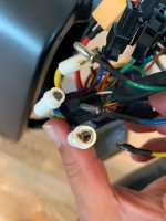
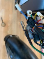
Those are the phase wire connections from the controller to the motor.

I can't tell the type of connection; it's different from any of the ones I've seen before, but it is probably some form of bullet connector, which uses a tube on the outside on one end and a tubular pin on the inside on the other end. Normally either the pin or the tube have one or more splits in them to act as a spring...and if the material is not springy enough, it makes a bad high resistance connection, which results in significant heating at the connection that can be like what you see there. A poor crimp of the bullet onto the wire does the same thing.

the color of the metal on the tubes looks like it has changed on the blue and yellow phases, but the green looks like it hasn't heated, so most likely it is just the blue and yellow connections that are damaged.

If you can unplug the three connectors, please do so and take a good image of each end of them, we may be able to tell more that way.

It is not likely taht there was any short, unless the blue and yellow actually melted thru their insulation and allowed conductors to touch.


However: It would be unusual for this type of problem to just happen to manifest right after the bike was worked on, unless it was exacerbated by the cable being disconnected and reconnected, or some other mechanical change at the connector itself.

It *could* be that there is a higher resistance there than there should be, but still very low...but that the new rear (or front, or both) brake drags a bit, causing the motor to have to make more power than normal and heat up more than normal, and also greater heating at all connnections, then the higher resistance of those two connections would create more heating there than normal, and begin to melt plastics, etc.

But it's all speculation right now.


The error 30 is *still* almost certainly a comm error, and if so is still one of the problems described previously, separate from this one.


The only potential commonality they would have is if this melting is caused by overcurrent due to internal motor or controller phase winding or FET shorts, which then blew out the controller's MCU via battery voltage feedback thru the FET gates (this *has* happened before). Then the MCU couldn't talk to the display, and the display would give a comm error. THe MCU also couldn't do anything else, and nothing on the system outside the display would do anything.
 
Upon pulling the three wires apart, the green is shiny and came apart correctly The blue was blackened and difficult to pull, but it did come apart. The yellow was blackened, melted, and could not be pulled apart. The wire severed at the plastic plug. I think we are in trouble at this point. And there is no way to know what my LBS guy did, or if anything he did was causational.
 

Attachments

  • m15.jpg
    m15.jpg
    74.7 KB · Views: 6
  • m16.jpg
    m16.jpg
    71 KB · Views: 6
Well, you can fix the phase wire connections, either by directly splicing them together or by replacing the connectors with something else (like RC Bullet connectors, or the same "automotive" bullets it is already using).

But...what was the results of testing the display-controller connection?
 
I replaced the burnt yellow; the blue was functional. Thanks for asking AW...we couldn't get a conclusive reading on anything else. This controller is split into two sets of wires; one appeared to be headlight and horn; seemed like a short to the headlight. As to the other side, we got an Open Loop reading. I can't work on it today but I am encouraged by the voltimeter. Perhaps illogically, I think I am going to jump in with all four paws here and order a set of levers with the brake cutoff port and restore the bike to original function, then start with the multi meter. Somewhat to amuse you, my father-in-law is a Ph.d with an undergrad in EE. I asked him a few questions. He said, buy a new bike. HAHAHAH.
 
This controller is split into two sets of wires; one appeared to be headlight and horn; seemed like a short to the headlight.

There will be a cable specifically to the display itself. That is the cable you must check to solve the error 30 if it is the comm error that every other display I've seen like that uses. At the controller end, it could be combined with other functions like throttle and brake lever, but normally it is a completely separate cable. It will be separate at the display itself, and split off from anything else at some point on the way up there.


As to the other side, we got an Open Loop reading. I can't work on it today but I am encouraged by the voltimeter.
Open Loop? If this was OL on the meter screen, it means OverLoad, or Out Of Range for the specific range chosen on the meter. See your meter manual for the specifics of what it means for the exact thing you were measuring at the time.

What was the specific reading, using what specific setting on the meter, with which specific meter lead connections at the meter and to what points on the bike?


BTW, if you don't get 5vdc, with the meter set to 20vdc, black lead from meter ground / common to battery negative (or any other ground wire on the controller, often black but not always), red lead to any of the 5v wires (should be one on the PAS sensor connector, and one on the throttle connector, and one on the motor halls connector, usually these are red but not always), when the display is turned on (with or without an error code), then the controller brain is not turned on and it will not operate, and is probably why the display is giving the error 30.

Perhaps illogically, I think I am going to jump in with all four paws here and order a set of levers with the brake cutoff port and restore the bike to original function,

The brakes almost certainly don't have anything to do with the error. (unless your bike manual says otherwise, it's safe to assume that error 30 means the display can't talk to the controller).

Note that when you replace the hydraulic levers, you will need to re-bleed the brake system, so have the manual for the brake system handy along with the bleed kit. If you don't, you'll probably have air in the lines and a failure of the brakes to work correctly later when you need them.

You'll also need to make sure the switches in the new levers are the same kind and wiring as the old levers, and the connectors are the same. If they are not, you'll have to rewire them to compatible connectors in the correct way, or replace the switches in the new levers with ones that are compatible to your system, etc.

It'd be safer for your braking system (assuming it is working correctly now) to just disconnect the levers from the system, or take the switches out and mount them so they can be manually released when you want them to engage, or one of the various other brake-switch methods suggested (or available elsewhere on the forum).
 
Back
Top