Need to cut or retro-fit external brake cutoff sensors

54Goldtop

10 mW
Joined
Aug 29, 2023
Messages
20
Location
Fiddletown. Fiddling around.
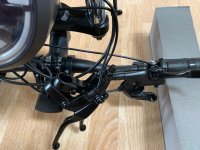
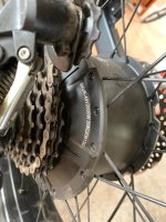
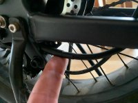
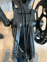
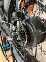
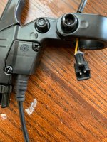
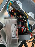
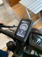
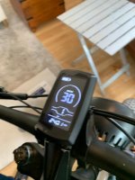
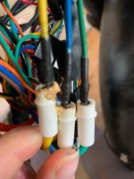
First, I have read a number of posts on this Forum as well as googled and watched several Youtube videos. My specific problem doesn't seem to be addressed so I thank all of you in advance. I have a Mao Tse Tung special ebike, which has about 250 miles on it, and the bike has been interesting and I decided t o add some upgraded parts. The bike is a beast, more like a Honda Trail 90 than an MTB, 2000 watt, 48 V, 25 AH as basic configuration. It has a no-name engine--"SKUK". It is crude but interesting and did work well. I upgraded the brakes and my LBS guy, who I like, put on a set of hyrdalic brakes that did not have the brake cutoff sensor port. He took the old levers and zip tied them to front fork, hillbilly solution. It worked for one ride. There is for sure a connection happening because if I move the zip tied (old) levers, the brake light will go on or off. The display shows an Error 30 code. My goal is to identify an external mount and use the existing sensor, or, switch out the sensors now, get rid of the old levers (ridiculous solution anyway) and tie them off--effectively removing them. I ride this boke on old fire roads and offroad trails, no city riding--I really don't think I need the cutoffs. Can someone suggest a way to either mount an external cutoff sensor or tie them off? Obviously, if they are tied off, I have the concern of interfering with some other grounding or reading that effects something else, electricity being magic and mysterious. it appears that no juice is getting to the rear hub engine. Where do I start?
 
One further idea that I have been kicking around, which means throwing good money after bad, if taking off the new Shimano brake levers and putting levers that have the sensor. But as we say in boatbuilding, for every solution two problems...
 
These work well with hydraulic brakes:
You may need to fiddle with them a little to determine the best alignment, but it's more like a 15 minute job to install.

I used hot glue to temporarily install them for testing before attaching the magnets permanently.
 
Last edited:
I upgraded the brakes and my LBS guy, who I like, put on a set of hyrdalic brakes that did not have the brake cutoff sensor port. He took the old levers and zip tied them to front fork, hillbilly solution. It worked for one ride. There is for sure a connection happening because if I move the zip tied (old) levers, the brake light will go on or off. The display shows an Error 30 code.

Error 30 is usually a communication error between display and controller; if so it doens't have anything to do with the brake sensors. It usually means that the cable or connector between display and ocntroller has a conneciton fault in one of the two TX/RX lines between them, and usually causes no or wrong data to be displayed on screen, or no or wrong settings to be applied to the controller, like being unable to change assist levels, etc. Can be damaged (pulled, cut, pinched, etc) wires, or connectors not fully plugged in.


If you don't need the brake sensors, and don't care about the brake light, and will just use hand signals instead, you can simply remove the brake sensors / old levers and their cabling. You can use heatshrink or tape or whatever you like to cover the ends of the connectors if you think they might accidentally get stuff in htem that could engage the brakes.


There are off the shelf hydraulic ebrake switches that get installed in your hydraulic cabling, but this requires you re-bleed the system too. (I think Tektro makes one, and maybe Hayes; they should show up in the above search. ) There's at least one thread around here with a DIY version.

Otherwise, the tripwire from Grin Tech is one of the simplest solutions you can get off the shelf as it doesn't require modifying the brake system itself.

Bafang makes one too, as do others, some of which turn up in this search
in the various tabs google presents for results
like this one

There are quite a few DIY solutions posted over the years as well, that apply not just to hydraulic brakes, but to any brakes, mostly using magnets on the lever and a reed switch on the body; these are essentially the same as the Bafang/etc add on solutions.
 
Add on brake switches. There are several variants if you go up one level in the URL:
 
Thanks Amberwolf. That is a lot of info. My LBS guy had problems every step of the way on this, and candidly he did not want to work on it. His shop doesn't service or sell these oddball Mao specials, and he said he also could not get the rear wheel off (to change the brake discs). he said there was no way to disconnect the main hot wire coming into the hub without taking apart the entire wiring cable harness. Which I infer that he tried, and that might be causing the E30 code. Uggh. This is a bad case of leaving well enough alone. The bike was operating perfectly but then I wanted to upgrade. So tonight I am going to start taking things apart and/or off. My wife is a phyiscs teacher who approaches every problem with a voltimeter, so she will assist until it gets too time consuming or annoying.
 
and he said he also could not get the rear wheel off (to change the brake discs). he said there was no way to disconnect the main hot wire coming into the hub without taking apart the entire wiring cable harness.

There is almost certainly an easy to unplug connector right there at the motor itself, probably ziptied to the frame near the axle. The "pictures" on the ebay ad appear to be illustrations or 3d models rather than actual photos, as they don't include a number of things that almost certainly are there on the actual bike.

This page shows some really common connectors types you may have on there:


If you can post clear, focused, well-lit (direct sunlight is best) close-up pictures of each area of the bike, we can point out where these connections might be for you to check.


Which I infer that he tried, and that might be causing the E30 code. Uggh. This is a bad case of leaving well enough alone. The bike was operating perfectly but then I wanted to upgrade. So tonight I am going to start taking things apart and/or off. My wife is a phyiscs teacher who approaches every problem with a voltimeter, so she will assist until it gets too time consuming or annoying.
Before taking it apart, post those pics so we can point out things to make it easier for you. ;)
 
I haven't yet started to disassemble. Here are some photos which, IMHO, don't show much. As mentioned above, I am not criticising the guy that did this work--he didn't want to work on it, but we have something like a friendship and I pushed him a bit. So...The first photo shows the hillbilly solution to the brake cutoff sensors. I observe that with the bike turned on, the rear brake will come on and off which suggests that the cutoff is intermittently interrupting power. Not the main problem, but a secondary problem. The main problem is now I have zero power, at all times, to the engine. This photo is a mess but it shows what I have on my hands.
 

Attachments

  • m1.jpg
    m1.jpg
    122.9 KB · Views: 7
Next, a photo showing the main vein, I think, coming into the engine. I don't see any other wire coming in and this one is heavier than the derailleur or the brake line. Process of elimination. I have my finger on the wire in the photo. There is no visible entrance into the hub, but it has to be coming in at that point.
 

Attachments

  • m5.jpg
    m5.jpg
    87.3 KB · Views: 5
This photo is important. It shows that there is no quick connect to separate the main input wire at the rear wheel. My son has a Lectra and it is a quick connect joint about halfway along the lower rear fork mainstay. Mine does not have this.
 

Attachments

  • m6.jpg
    m6.jpg
    109.7 KB · Views: 4
Last edited:
Tonight I intend to open up the main hatch and check for any loose connections around the controller/BMS box. But for sure, I have two overlapping problems: the brake cutoff sensors and the fact that now I have no power at all at the wheel. I think I should at least have intermittent power to the engine.
 
This is the computer (BMS?).
That is the controller (sometimes called ESC, electronic speed control).

The BMS is inside the battery pack, as it is a Battery Management System.

Error 30 is communication failure between the controller and display. It means that the display does not get (a correct, or any) response from the controller when sending data to it.

Assuming this is the same display and controller the bike had when it was working, and nothng was changed out, then:

Could just be a connection fault, either the connector between display and controller not plugged in fully, or a contact in the plug that has spread out or misaligned, etc. Most common.

Could be a wire broken inside the cable on either side of that connector. Next most common.

Could be that the controller is not getting turned on by the display--these systems work by the display being powered all the time by the battery voltage to the controller then to the display. The display's power button turns on a transistor switch inside the display that then sends battery voltage back to the controller, which powers it's LVPS that makes 5v, 12v, etc to run the controller brains whcih turns on the whole system. Usually if it is not a connection fault (see above) then it is the transistor failed inside the display. Third most common.

Could be an electronics problem in controller or display, wehre the TX or RX buffer in either one has failed. Least common.


Since your bike was just worked on and stuff was moved, handled, etc., in ways you probably can't know about, the most likely cause is one of the first two.

THe only good way to test for a connection fault other than unplugging and replugging just the connnector from the display to the controller, and ensuring it is seated fully, is to open both display and controller and do a continuity test for each of the (probably five) wires in that cable from the actual PCB inside each one where the wires solder on.

Since that is difficult and can actually break things worse, it's better to first eliminate one of the other related problems. This is done by using a voltmeter set to 20VDC. If you can access the pins on the connector without unpluging things, do so, but otherwise unplug the throttle or PAS sensor from the controller. Turn the system on. Connect the black meter lead to any of the controller-side pins of that connector. Touch the red lead to each of the other two pins. Move the black lead to either of the other two pins. Touch the red lead to each of the other two pins. You should get 5v across at least one pair of those pins. If you do not get any voltage on the pins in any combination, then the controller is not getting turned on.

If it isn't getting turned on, then either there is a connection failure between controller and display, or display's transistor is failed.

A similar test to the 5v test can be done at the display connector, but because it requires you to also connect battery voltage, it is a riskier test as one slip or misconnection can destroy the display (and/or controller, etc). So we'll leave that test until it has to be done.
 
Back
Top