they probahbly mean low-level brake, which is one that grounds the signal line from t he controlelr, which is how most of tehm owrk.
some contorllers have high level brake, which takes 12v ffrom an external source to turn on the brakes, for scooters and motor cycles athat have 12v lighting and use 12v to turn on their brake light.
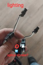
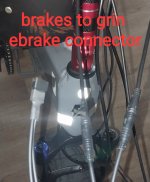
so you should be able to wire the brake signal (not ground) from your brake levers to the light kits brake input, and to the ocntroller too if you want the brake to operate the controllers ebrake. if the rtr kit has the brake lever signal going to the cycle analyst you can still wire the lghts brake input to that as long as the light kits brake input just needs a grounded input to turn it on and doesn't place any voltage on that input wire.
you can take a look at my sb cruiser thread for how i lit it up, start at the end and work your way back since it's changes lots over the years.
i'm using plain color strips for static marker lights on fork/etc, and also using car add on turn signal strips that are white front red rear always on and when turning flash amber sequentially to really grab your attention. the rear ones also have a brake light functiont aht brightens them and flashes them rapidly a few times. i have them mounted up high on the rear edge of the cargo rack frame where ven tall suvs can seethemn.
plus i have trailre lights on the back of the tirke for regular turn signals, brake lights, and tail lights because the're big hand-sized things that even car drivers will notice even in daylight instead of teensy xmas bulb sized things that they can ignore.
then i used osme white downlighting on the sides to light up the cargo pod sides, and some on the downtube to light up the raod under the trike itself, and a rear red light under the back end to light the road up under the cargo pod.
and there are white lights i can turn on to light up the deck too, that shine forward from the rear rack onto it, and there are white lights i can shine down onto me form the canopy top to lght me up, but those two i don't normally need.
i'm also using a car headlight rather than a lttle led thing because i can see well with it and it doesn't blind anyone but it's a power hog.
i have a separate battery for the lights so that even if i run out of mtor power i still have lights to be seen with.
")
if you mean you could turn the lights on by turning on the display backlight / headlight conttrol, then if the enw dsiplay has a wire for that you coudl try it, but most of those only put out a tiny aomoutn of power and more than a tiny headlight may blow up t he internal transistor that does the switching.
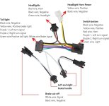
you can use a separate switch to turn the lgihts on by hooking up one side of the switch to the battery positive, and the other to the light kit positive. light kit negatove/ground goes to battery ground.
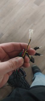
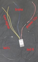
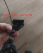
i'm too tired to draw up the connections on the harnes picture now, but i'll give it a go when i'm more awake probably later this week smetime. .
if the motor was geared and had a freewheel (easy to turn it forward, not as easy backwards) then no matter how fast you pedal it would never regen. if it does not have a freewheel (same force to turn forward as backwards) then it could regen if you pedalled the bike faster than the motor could spin at the battery voltage you were at at the time, even if the bike had no regen option. but unless you can pedla a fair bit faster than the motor can push oyu it wouldn't generate much, and it would be a lot harder to pedal while it was doing this.


 . The old motor was a freewheel geared motor and I didn't think it was doing any regent, long story short on that is I got a full refund on the bike and was able to keep it.