
Last week my VLCD5 display got stolen, I bought another VLCD5 display (2nd hand) but it's not plug and play.
My working setup was: TSDZ2 36V, VLCD5 6pin. VLCD5 firmware 3.7
I bought a VLCD5 48V 8 Pin. VLCD5 firmware 5.0
I was thinking I could just hotswap the displays, since they have the same 6pin connector, but that doesn't work for me, the motor doesn't give support:
The bike powers on, and I'm able to navigate through the VLCD5 menu.
The battery indication is wrong; While my battery is 95% full it only shows 1 bar.
There is no support, the motor is off (feels like it, no noise etc.)
- Is the VLCD5 not swappable between 36V 6pin and 48V 8pin?
- Is the difference in firmware causing the issue?
- Is it normal that 1 of the pogo pins isn't connected?
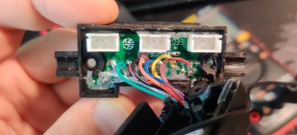
I opened my display and the connector, and noticed that the first pogo pin is not connected to the cable (attached image:"the pad left to the green wire).
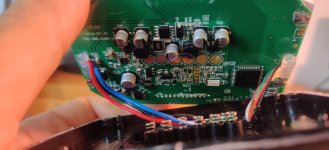
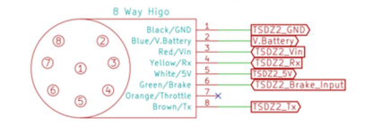
I also attached a picture of the VLCD5 pcb, and the pinout of the 48V 8 pin connector (female).
I hope you guys know more.
My working setup was: TSDZ2 36V, VLCD5 6pin. VLCD5 firmware 3.7
I bought a VLCD5 48V 8 Pin. VLCD5 firmware 5.0
I was thinking I could just hotswap the displays, since they have the same 6pin connector, but that doesn't work for me, the motor doesn't give support:
The bike powers on, and I'm able to navigate through the VLCD5 menu.
The battery indication is wrong; While my battery is 95% full it only shows 1 bar.
There is no support, the motor is off (feels like it, no noise etc.)
- Is the VLCD5 not swappable between 36V 6pin and 48V 8pin?
- Is the difference in firmware causing the issue?
- Is it normal that 1 of the pogo pins isn't connected?
I opened my display and the connector, and noticed that the first pogo pin is not connected to the cable (attached image:"the pad left to the green wire).
I also attached a picture of the VLCD5 pcb, and the pinout of the 48V 8 pin connector (female).
I hope you guys know more.
Attachments
Last edited:


