Nucular Electronics owner's thread (setup infos, FW updates, links etc.)

Yes, must be the BMS of my stock Battery that cuts off.
I changed in the controll modes battery S1,S2,S3 under 90A.
Befor battery S3 was over 90, sorry didnt note it.
I will report when I did a testrun.
And yes, a new Battery will be the next upgrade.
I just joined the telegram group.
 
Has anyone connected their controller to a bafang ultra m620 yet? I'm thinking of connecting my 12F to one. I guess you need to run sensorless sense the ultra uses some weird magnet thing instead of halls. Will it be as easy to get running as my qs1000 was besides the no hall sensors issue?
 
I think I have the answer to this, but just want to confirm.

I want to have a wrist-tether kill switch on my bike so when I come off, it stops - a rule of competition.

I think the correct approach is setting an I/O for DM (disable throttle, brake and PAS). Even if the throttle is at full power, when the I/O gets closed the controller will happily cut everything off?
What will happen if the switch is then reset while the throttle is, say, stuck open? Will the bike immediately GO, or will the controller do the power up throttle check and not start until the throttle is brought back to 0?

Also wondered what the effect of connecting the switch to the "Remote - enable switch" would be? I'm guessing that at best that would be inconvenient (have to reset speed mode after each stop) and at worst might be potentially bad for the controller turning it off at full power.

The last option is to have the tether open an isolator/circuit breaker in the battery circuit. This would be nice in that the tether would be a somewhat complete cutoff in case of disaster somewhere in the electrics. Again, I'm not sure how the controller would like suddenly having the battery cut off at, say, full power?

Thanks.
 
To connect directly to the controller the pas, throttle, cruiser, 3 positions button, brake etc. must be opened? I do not see them outside.
 
Dear ebikers,

I had to postpone my project for months following family issues. I have a 12F controller form Nucular and it will drive a MXUS 4t hub motor. I built a 20s 14p battery. Excuse me if I have dumb questions but the last build I done was very easy (Em3ev) for connections.

Question 1
https://torquetech.co.uk/collections/throttles/products/electric-bike-thumb-throttle-12-84v-led-display-voltmeter-on-off-kill-switch?variant=10154897637423
throttle on off switch.JPG
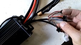
I want to connect to this controller to a Thumb Throttle 12-84v with an ON OFF Kill Switch (green, red, black, yellow and blue cable). This throttle is delivered with a JST-XA connector (2.5 mm pitch). The Nucular controller accepts JST-PA connector (2 mm pitch). So basically, I cut off the JST-XA connector and crimp a new one as in the picture.
Red goes to +5, green is the throttle signal and black is ground.

The switch ON/OFF has blue and yellow cables. I don’t want them to connect them directly to the battery. I can connect them to the ‘remote connector’ of the controller, cut their terminal and crimp a new JST connector. So, the yellow cable goes to K1 and the blue cable to the ground. Am I right?

Question 2
https://torquetech.co.uk/collections/switches/products/handlebar-3-speed-position-spdt-switch-hi-med-low-electric-bike-ebike-scooter-uk?variant=10154897801263

Then I need to connect the Handlebar 3 Speed Position SPDT Switch HI MED LOW. Here it is the same issue. It is delivered with a JST-XA connector with 3 cables, red, green and black. Where do I connect this switch? To the ‘speed sensor’? But from the diagram, it seems that only two cables are used. which ones should I use? Black connects to ground and green and red cables both connected to SP?

This is the description of the connection from torquetech.co.uk

Pin Connections:
Position 1 (Low speed): Green to – Blue
Position 2 (Med speed): Black to - Black
Position 3 (High speed): Red to - Yellow or Green depending on controller
SPDT Switching Pairs:
Position 1 (Low speed): Green & Black
Position 2 (Med speed): No connection
Position 3 (High speed): Red & Black

Question 3
https://lmxbikes.com/en/chassis-parts/83-trp-zurich-brake-set-for-lmx.html
ebrake TRP Zurich.JPG
Then I will connect the Trp Zurich ebrake, the same one used by the French company LMX64. There are 2 pins. I guess will connect them to the connector labelled ‘brake’. One pin will go to the ground and the other one to IO8. I guess there is no polarity so I don’t care about which pin will go to the ground or IO8? Right?

Question 4
https://www.alibaba.com/product-detail/electric-bike-accessories-cruise-control-for_60081909479.html
I will add a cruise control as for long ride it is better for my thumb. I have not yet ordered it but it will be this one:

From the image one can notice 5 cables:
Black and red together and
Black, white and yellow together.
Is the black and red going to the ebrake connector?
I guess I have to use the I/O1 connector with black going to the ground and the other colour? Can you please let me know?
cruise control.jpg

Many thanks for your comments and keep safe.
Pierre
 
Hello!
Q1) correct

Q2 same as Q3) use any IOn port as input, speed sensor is wheel speed sensor. Configure display buttons as CAN1/2/3/whatever (http://wiki.nucular.tech/en:display-setup#toc9) and setup needed function in controller-port configuration. for 3sp switch there two modes - 'S1of3' and 'S3of3' (http://wiki.nucular.tech/en:controller-setup#toc26), two wires go to IOn, one common wire to GND
Q3) for brake you can setup 'brake' function in display for selected port. polarity - any

Q4) idk how this cruise thing works, need scheme, but you can also use hotkeys to enable cruise
 
Peterfr12 said:
The switch ON/OFF has blue and yellow cables. I don’t want them to connect them directly to the battery. I can connect them to the ‘remote connector’ of the controller, cut their terminal and crimp a new JST connector. So, the yellow cable goes to K1 and the blue cable to the ground. Am I right?
Why you wanna use a throttle with built in voltmeter if you have display already showing it?

I recently installed similar throttle and the blue wire is here internally connected to this voltmeter, and GND it takes from hall sensor black wire.
That might not be a problem but it cannot harm to open it and cut this connection between sw and sensor.
 
Anyone had issue using the Dimono Throttle, Seems to Fulate Voltage and makes motor souund like its trying to move, it doenst have enough voltage to move, I have trieed changing the Throttle MV but no luck.

Any ideas

Maybe its the throttle as it also just tap throttle and ramps voltage, not full throttle but 500w etc can you turn that down already have it set to speed and tourque, sounds like my motor is shunts when i take off.


Cheers
 
Merlin said:
yup. there are some issues with dominos.
try to put 250ohm resistor to gnd and 5+

Sweet Man ill give it ago, Im sure it never used to do it why i thouht maye it was setting, as i have been playing around with Min and Max mv

Yeah ill try it.

cheers heaps
 
Guys

I have been trying to figure out the Delta Voltage, how does this work IE i set to my batteries to charge to 4.1v
IE and my Battery Charges to 83v the Controller is out little like .7 v

I have tried defualt Delta but doesnt seem to work.

Can anyone help me with this one, Its bit annoying to reset the WH every time i charge.

Cheers
 
If you charge to 83v and you set delta to 2.0v it will reset wh at 81v (needs power cycle)
If you have 0.7v difference in display just calculate it difference in display to real voltage than put that on top
 
From the Nucular wiki: "delta voltage relative to the maximum, at which when the controller is turns on, will reset the watt-hour consumption".

The way I read that, is if you turn on the controller and you battery voltage is between Vmax and Vmax-dv, your Wh will reset.

Your Vmax should be set to 84V for a 20S pack. Try setting dv to 2 volts. Then if you turn on the controller, your Wh should only reset if your battery is above 82v.
 
I'm in the process of placing a preorder for a 24F and could use a better understanding of a few things.

Optional CAN cables. Where are these used? Just want to make sure I order them if I'm going to need them.

Optical Isolated PWM driver. Pretty sure I want it, but I could use some clarification on exactly what it is and how it works. :lol:

Optional controller side inputs. I don't know that I'll need them but they might come in handy at some point. Any reason I wouldn't want to add these? Also curious as to exactly what you get. A bunch of individual wires coming out of the controller, single cable with smaller wires inside, bare ends, connectors. Just trying to visualize it.

I'm sure I'll have more questions, but that's a good start.
 
I think the can cables are if you want to connect other things to the can bus, except the controller and display.
Pwm drivers, if you want to connect fans or brake light etc to the pwm outputs.
Controller side inputs, if you want to connect brake, throttle etc. to the controller. Normally they are connected to the display.
I think all that information is on their website

If you want to use the pwm outputs, make sure you get wiring for them. Especially if you get a potted controller..
I ordered the extra side inputs, believing I would get all the extra wiring for the controller. But that was not the case, pwm and everything else in the same contact housing was not included. I think you need those contacts if you will be using a torque sensor too.
 
Awesome, thanks.

When you said to be sure to be sure to get the pwm outputs, is that the same as adding the PWM IO PAS wire option, or something different?

I don't really understand how the pwm driver thing works. I know what pwm is but am lost in regards to how it's used in this application for fans and lights and such, and the 30v notation just confused me further. Could really use some help wrapping my head around it and how it all ties together.

Also wondering, are the controller side input wires a bunch of individual wires coming out of the controller or were they contained in a signal conduit? Any connectors on their ends as shipped?
 
Hi VasiliSK

Do you have any experience running big RC motors with your controllers? Such as Turnigy CA120 outrunner with low inductance values? What pwm frequency can/do your controllers run at?
Please share any working examples or owner threads of such combinations.
Thank you

Cheers
Tyler

 
HK12K said:
Also I wondering, are the controller side input wires a bunch of individual wires coming out of the controller or were they contained in a signal conduit? Any connectors on their ends as shipped?
Yes there are several wires for the connection of options on the controller. It is very convenient to connect. If you prefer something discreet and very few wires, don't take this option, because you can all connect behind the LCD screen.
In the photo you can see the wires in my hand.
 

Attachments

  • IMG_20200416_221619.jpg
    IMG_20200416_221619.jpg
    73.1 KB · Views: 1,362
Back
Top