Open source on Lishui LSW6G-90B-FOC-171215.

moriamoria

100 µW
Joined
Dec 28, 2023
Messages
9
Location
paris
Hello every one,

After briking a kt 48ZWSKT-SJT02L where I have flash with stancecoke/BMSBattery_S_controllers_firmware (even after install a current sensor), I decide to floow "stancecoke" advise on a precedent post and to go to a lushui controller.

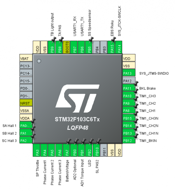
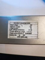
I have found a LSW 667-31F 36v controller (I just have to change one FET that is HS). the motherboard is LSW6G_90B-FOC-171215

on this motherboard, I think the specification for open source looks ok :

STM32FEB KC6T6
1* LM317 regulator
3* FD03S
C34 H91C
....

After the story, my questions :

  1. Can any one send me the stock firmware and the tools to set properties on the current firmware.
  2. Is it a good controller for EBiCS_Firmware
  3. Can I use a KT lcd3 display on it.
  4. Could you confirm that I need to add a DC to DC converter for a bluetooth adapter?
  5. I have a 48v battery, and the resistance for the board power supply is 100 homs, Do I need to adjust it ?
  6. Finaly I will use a magnetic pedal sensor. Ok for that ? I think stanceoke sais it was ok.
Many thanks for your return.
 

Attachments

  • IMG_20240114_150112.jpg
    IMG_20240114_150112.jpg
    2 MB · Views: 7
  • IMG_20240114_150040 (1).jpg
    1.4 MB · Views: 10
  • IMG_20240114_145943 (1).jpg
    1.2 MB · Views: 6
Last edited:
Hello,

I had make a mistake on the board reference, it is :

LSW6G_90B-FOC-171215

Thanks for your help about setting a open firmware, and if possible got a stock firmware.

Regards to all from Paris France
 
Please read the wiki at github, how to configure and flash the EBiCS firmware.

If you still have questions after reading the wiki, don't hesitate to ask here.

regards
stancecoke
 
Hello,

Thanks for your answer, I had already flash a KT controller, it was easy, but this was a wrong controler (square ) and I have create a brick !

Before doing the same with this Lishui controller, I like to have a stock firmware.

Any one has a firmware from Lishui ?

In any case thanks stacecoke for your support. I will start right a way.

Regard to all
 
and I have create a brick !
Why? You just have to disable the angle optimization. Then the firmware works with the square wave hardware, also. Just a little less efficient. Motor halls required.

For the Lishuis, there is no public official firmware available.

regards
stancecoke
 
Hello,

I am trying to connect my new lishui controller to my old byke.

It looks like on the Lishui controller, we have 4 hall sensor (). But on my bike and on the KT controller, I have only 3 hall sensor. Is it a problem(red black blue green yellow).

I need also to connect my lcd3 display to the Lishui controller, but it seems that I have 6 wire on the Lishui (Red black yellow green blue white) and on my kt controller/ old byke, i have (red blue black green yellow) 5 wire.

After, I have on the lishui a "julet" connector with 5 pins, it is connected to the motherboard as :

white connected to AD1
blue not connected
yellow to ebs
red and black to power line.

And to finish, I have a KM4 connector

yellow to rx (also connected to power suply connector)
green tx (also connected to power suply connector)
blue light to sw
red vb+
black vb-

So I am looking for a pinout plan to connect all that stuff to my old bike.

Any idea ? Helps

Many regards
 
So I am looking for a pinout plan
Obviously you haven't read the wiki yet. ;)

regards
stancecoke
Pinout%20Old%20Generation.PNG
 
Hello,

You are right.

I have download the git and I was looking to pinout.

  • The pin our shows only 3 hall sensor, so one of the 4 wire must be unused.
  • I suppose that SYS_JTMS_SWDIO and SYS_JTCK_SWCLK are pin used to flash the controller, I will connect them to the programmer ST LINK 32
  • Regarding LCD3, I think that USART T1_rx and USART T1_tx goes there. Also the configuration tools offer Kunten display. Should be ok.
  • lishui a "julet" with AD1 looks to be the torque sensor, I will not use it, only PAS

for the
KM4 connector

yellow to rx (also connected to power suply connector)
green tx (also connected to power suply connector)
blue light to sw

I am lost for the moment, but I will read the code file and the wiki.

Regards
 
I am lost for the moment
:)
Your controller model seems to be quite special, having the UART1 lines on the battery connector in parallel to the display is strange. Are you sure, that it isn't UART3 like in some new generation PCBs?
Of course you can build some kind of UART bus with various members like controller, display and battery BMS, but that will not work with "normal" display protocols.
But don't mind, the EBiCS can be configured to work with you hardware surely.
The white wire on the motor connector is for the speed signal normally. So it should be connected to the SS pad on the PCB. Sometimes it's used for the temperature signal, then it's attached to the AD2 pad.

regards
stancecoke
 
Last edited:
Back
Top