Piaggio Ape conversion – Advice appreciated

tndr_1

1 W
Joined
Oct 11, 2022
Messages
51
Location
Stockholm
Was: "Need help wiring brushless controller"

Hello there! :D

First time poster, and also first time actually wiring anything related to an EBike. My project is actually an Piaggio Ape 50 with a 48W 1kW brushless motor :) I just got the vehicle a couple of days ago and the previous owner has removed all the wiring so I have to redo everything.

My issues:
* No smooth start
* Low top speed (haven't measured)
* Controller gets super hot after 1 minute of driving so I feel the need to turn it off manually (no other cooling than the controller chassi)

Brushless motor controller 2-mode (https://www.amazon.se/gp/product/B0816NS8QM/ref=ppx_yo_dt_b_asin_title_o00_s00?ie=UTF8&psc=1) (I can not find any instructions)
Battery voltage: 48V/60V/64V
Current limit: 26A-30A
Phase angle 60/120 degrees automatical identical level

The vehicle has both parking brake, and foot brake. I have no instructions at all on how to wire the controller and the information I can find by Googling never seems to be related to my controller.

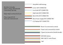
Anyways. This is how I have everything wired up today. As u will see, I have the (for some reason) dreaded Power Lock (which I have to connect to be able to run the engine). You can also see that I have no brake wires connected. It feels like I need to have them somewhat under control, but I don't know how?
Skärmavbild 2022-10-11 kl. 14.31.43.png

I have no experience in controllers like these, so I am very grateful for any help I can get :)

/ Oskar
 
You need to find the correct combination for the Hall sensor wires and phase wires. The wire colors from the controller to the motor seldom match. There are some combinations that will spin the motor but use way too much current. I would guess that is your problem. If I remember correctly there is only one wire combo that will spin the motor forwards and one that will spin it backwards. The rest of the combos will result in harsh vibration or way to much current draw.

This is a thread from the technical reference area of the forum with instructions on how to find the correct wiring combo. There is a helpful flow chart.
https://endless-sphere.com/forums/viewtopic.php?f=16&t=3484

I believe that white study/self learning wire is supposed to program the controller for you but I have never seen that work ever so I don't mess with it.

If you got it spinning then I would think your throttle wiring is correct.
 
Thank you! I will try to find the correct HALL wiring combo!!

This is my self learning procedure:
* Connect HALL/Battery/Throttle + Self learning
* If motor runs backwards disconnect self learning wires
* Connect self learning cables if motor runs forward.

But I will go with your approach now, and learn more about it!
 
So maybe self learning is just a poorly translated word for direction switching?

The first few controllers I had didnt have a learning wire so I just got into the habit of trying the combinations to find the correct one.

Maybe a coincidence but most of my controllers are correct when only one hall and one phase color match each other.

Just proceed carefully and make a chart to try them systematically to make sure you aren't repeating combos. Also go slow on the throttle so the incorrect combos wont spike the current too high.
 
DanGT86 said:
Just proceed carefully and make a chart to try them systematically to make sure you aren't repeating combos. Also go slow on the throttle so the incorrect combos wont spike the current too high.

As I said, my vehicle runs, but controller get really hot so maybe we can suppose that is one of those where it runs but draws too much power. Would that also affect top speed? I feel the top speed is really not 25km/h as seller announced.

I will do this testing tomorrow. Thanks!
 
First: It sounds like you have a project that someone else started, and you're trying to get working using the same parts they already had. If this is the case, it's easily possible that something is damaged, possibly just wires or connectors, but possibly something in the motor or the controller itself.

But, I think your system might just be overloaded:

It may take more than 1kw for a Piaggio Ape 50. That's a pretty big vehicle for that amount of power, even on flat roads, unless you are going pretty slowly and not accelerating quickly.
https://www.google.com/search?newwindow=1&source=univ&tbm=isch&q=Piaggio+Ape+50
https://cdn-fastly.thetruthaboutcars.com/media/2022/07/19/9357957/review-piaggio-ape-50-europe.jpg?size=720x845&nocrop=1
review-piaggio-ape-50-europe[1].jpg

I did find a spec sheet for the 2018 model:
https://piaggiocommercialuk.com/wp-content/uploads/2018/01/Ape50-Brochure-EN-2016.pdf
View attachment Ape50-Brochure-EN-2016[1].pdf
that say's it's 50cc 2-stroke engine has a max power of 1.8kw at 5500rpm, and only makes 3.3Nm of toque at 4250rpm, and only lets it reacha speed of 38km/h. Curb weight (empty) is 510kg, or over 1000lbs.


Depending on where your motor is mounted and whether it goes thru any gearing (especially a transmission), I suspect you're going to need up to several times that amount of power to run it (depends on your goals and usage conditions), so both a bigger motor and a bigger controller. Possibly a bigger battery, depending on what you've got for that already.

I built the SB Cruiser, a heavy cargo trike, that probably weighs less than half what the Ape does and still takes about 4kw+ to accelerate from zero to 20mph in 4 seconds, without any cargo in it. Longer, with cargo. Only a little more than a 1kW to maintain that 20mph on average, sometimes as little as 800w, depends on the road and wind, but I'm always riding on nearly flat roads.


I suspect you'd be a lot happier with a motor/controller/battery system designed to run a motorcycle (geared down for the low speeds the Ape was designed for) than one for an ebike or small scooter.


If none of that is an issue, some things you might check: If the controller is not enclosed in a bag/etc and has airflow and still gets really hot, it is most likely a problem where it isn't driving the motor correctly, such as a wrong phase/hall combo...but:

The self learn function is intended to determine the wiring combo for you.

Usually you power on the controller, connect the two learn wires together, and it will spin the motor (usually slowly), sometimes making some noises or jerking, then smoothly spin in the one direction. Some controllers will stop at this point, and wait for you to disconnect the wire pair. Some continue to spin until you disconnect the wire.

If it spins in the wrong direction, just disconnect and reconnect the wires, it'll reverse the direction (assuming a direct drive hubmotor, and not a geared hub).

Sometimes you have to power cycle the controller after disconnecting the learn wires to make it "stick" before using the controller, sometimes it doesn't care.

I've had different results on different controllers, but so far the few that have had them did their job well enough. Some people have not had good results with some motor / controller combinations.


In cases where it does not appear to be working smoothly or properly like yours, you can determine the hall/phase combination manually (there's a few threads about it, some with charts to follow), but the controller itself is already trying all the combinations itself, so this is unlikely to solve the problem

It usually means there is some other problem, such as a hall signal problem, caused by a poor connection problem or failed/damaged hall sensor, or a connection issue with a phase wire. Mostly it's connection problems that stop things from working, things that look plugged in but aren't quite fully pushed together, etc., or broken wires inside a cable, etc.


But, you're in luck about the controller: it supports sensorless mode as well. Disconnect all five hall wires completely, then power the system on. It is now in sensorless mode, and if the problem was caused by a wrong phase / hall combo, the problme will be gone because it is not using halls. ;) If the controller stays cool, and the motor appears to work correctly at the right speed, then the problem is in the hall wiring or the sensors inside the motor, most likely (because the self-learn should've made it work correctly).
 
Yes, I have bought a project that someone else finished but removed parts (controller and batteries) from and sold.

I am actually a bit sad that I didn't realize that the motor would be a bit on the weak side. I paid not that much for the project, but a lot of energy has went into it already.
 
amberwolf said:
I suspect you'd be a lot happier with a motor/controller/battery system designed to run a motorcycle (geared down for the low speeds the Ape was designed for) than one for an ebike or small scooter.

Thanks for this advice! What do you recommend to start look at? Brands etc?
 
It depends on what exactly you need it to do for you, under what specific conditions, and how the motor is connected to the wheel(s).

Also depends on the actual motor that's in there now.

Can you post some pics of exactly what you're working with, including any labelling it may have?

If you define your usage case, it will help determine the power needed to do what you want. Desired speed, terrain to be used on, range and acceleration required, frequent starts/stops or constant-speed cruising, etc. Also whether you'll use it with just you, or additional riders / cargo, etc. Worst-case weight, etc., to get the worst-case power usage figures.

If you would like to see how these things all interact, you can go to http://ebikes.ca/tools/simulator.html , and see how much power it may take to do what you need using this vehicle.


If by "3-speed cables" you mean the three wires for a three-speed switch from the controller, that depends. Assuming the controller you end up using (if it's not this one) has that option, they typically just change the percentage of throttle response the controller does. The actual ratios used vary; some of them try to make them sound impressive by using greater than 100% for the high one, but this is impossible, you can't actually get more than 100%. ;)

Whether this is useful or not depends on the job the system needs to do for you, and the specific behavior of the specific controller's three-speed option. Most of these controllers use the throttle to control the speed of the motor, making the switch essentially a speed limiter with three max-speed settings. A few control the motor torque with the throttle instead, so it makes the switch a "power control", with three max-power (really, max motor current) limits. Your present controller probably uses the first method.
 
Thank you so much for spending time on answering!

I think this needs to be its own project thread indeed! :) To be able to fully cover issues and solutions!
 
If you like you can edit the first post to change the title of the thread to whatever the project name is (if it has one).


Then start posting pics and details here so we can figure out whatever solution works for you. :)
 
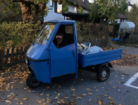
The beauty:
Skärmavbild 2022-10-25 kl. 14.40.15.png

Okey, so I converted this thread into a project thread now instead. The first controller I bought burned quite quickly and it was later confirmed that that controller was a 500W controller rather than 1000-1300W according to this review: https://www.youtube.com/watch?v=88SOQoiZzCU – That is fine. Lesson learned.

Issues:
* Slow top speed (13km/h)
* Can not handle a simple hill.

Possible causes:
* Bad controller which did not provide enough power/current?
* Bad wiring of hall-sensors?
* Bad battery setup? (12V lead acid batteries in series)
* Too heavy batteries?
* 1kW is not enough?

Please note:
* I inherited this project – I have not installed or picked the motor.
* I use lead acid batteries because I don't wanna invest in a LiPo battery until I for sure have a reliable setup!

So I have now ordered this controller which will arrive 12th of November: https://www.aliexpress.com/item/1005004105836465.html

The new controller is 60V-72V 3000W and I am hoping to have a successful overvolting of the engine. I am planning to have this experiment monitored and will be adding a DS18B20 temperature sensor as close to the stator winding I can.

I did some homework and I have weighed the vehicle empty and with minimal cargo.

Total weight empty: ~180kg (396 pounds)
Total weight with batteries+people: 350kg (771 pounds)

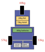
This is the weight distribution:
Skärmavbild 2022-10-25 kl. 14.35.32.png

Skärmavbild 2022-10-25 kl. 14.41.20.png

Skärmavbild 2022-10-25 kl. 14.41.02.png

Skärmavbild 2022-10-25 kl. 14.40.40.png


Skärmavbild 2022-10-25 kl. 14.39.57.png

Skärmavbild 2022-10-25 kl. 14.39.46.png

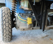
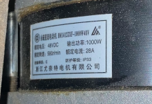
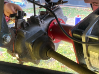
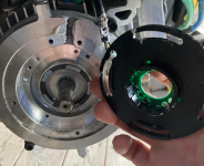
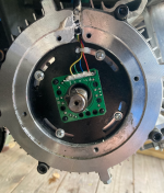
Above is some pictures on how the motor is currently installed. The motor RPM says 580r/min which and that is because the motor has planetary gears inside it.

My budget is approx $700 for the battery and if I need to replace the motor... Then I just don't know what to replace to. I know I can fix this with a tight budget, I just need your hand to guide me.

I have a MIG welder and a lot of other stuff to get. stuff. done! :lol: :D
 
Nice project, I was planning to convert an Ape 50 as well, but €1200 for a rusty chassis was simply too much.

I have a pit bike with a 1kw hub motor with a 48v 20A controller, and it just barely pulls me at 10kph :|
for such a mass, I recommend 3-5KW
 
eee291 said:
Nice project, I was planning to convert an Ape 50 as well, but €1200 for a rusty chassis was simply too much.

I have a pit bike with a 1kw hub motor with a 48v 20A controller, and it just barely pulls me at 10kph :|
for such a mass, I recommend 3-5KW

I bought the rusty chassi (fixed and painted) $630 including motor but nothing else.

Yes. The motor might not be enough IF I wanna have some cargo loaded. Which I want.

3000W seems like a good enough level. What do you think? It would really benefit from like 3 speed gears also, but I have not found a solution for that yet.
 
What do you mean 3 speed gear? Like the 3 pin connector? That will increase motor speed by 10% or so.
If the transmission itself has 3 gears, try running it in 1st gear, if you can.
 
No I mean like an actual gearbox. With three speeds. Or four or whatever :D

But they seem to be hard to find. I don’t know.

Also. It feels like 4-5kW really needs much more battery. Since they will draw much more current than 2-3kW… am I right in this you think?
 
Correct, you will need a battery that can handle that much power, I can help you in that regard.
 
The first controller I bought burned quite quickly and it was later confirmed that that controller was a 500W controller rather than 1000-1300W according to this review: https://www.youtube.com/watch?v=88SOQoiZzCU – That is fine. Lesson learned.
FWIW, the controller is what controls the power used, so it should not be damaged by being a lower power controller even if you have a load much higher than it can power. It should just not give you the power you need to do what you want, if it's properly designed. (of course, really cheap ones may not be).

The *motor*, if undersized for the power used thru it, could certainly get burned up.

The batteries, if undersized for the current pulled from them, will sag in voltage excessively and so the system won't have the speed it should. Lead acid probably won't be damaged by it (unless this is sustained long enough to cause enough internal heating to boil electrolyte) but lithium batteries can overheat and be damaged, or even start a fire if the heat/damage is severe enough...so it's important to size the battery to *easily* handle the full worst case load it will ever see, even as it ages.


* Slow top speed (13km/h)
That can be insufficient power (too small a controller) if the terrain, rolling resistance, wind resistance, etc. require more power to go faster.

Or it can be too low a voltage for the motor's kV (rpm/volt) / the wrong winding of motor (kV) for the voltage you have to use, to get the RPM output required to drive the transmission and thus the wheels at the RPM needed for the speed you're after.

(for instance, the max RPM of that motor at the voltage it's spec'd at 580RPM--if that is not as high as the original engine's output RPM, then this motor at this voltage will never go as fast as the original did, by the ratio of the new to the original RPM--I didn't look around ATM to try to find out what that original RPM is, but I'm sure it's out there somewhere).

When top speed is ok once it reaches it but it slows down on any even slight upward slope (worse the steeper it is) then it can also be battery voltage sag from insufficient battery capability for the power required of it (the battery must be able to supply all the powe the system will ever need, and preferably significantly (25-50%, at least) more so it is not under stress and can still do so as it ages).


* Can not handle a simple hill.
By "simple", what is it's slope and length?

You'll need to know those, plus the total weight of the vehicle and anything it must carry (including you), and the speed you want to maintain on the hill, to find out how much power it will require, at minimum, to climb it (you need the length to know how long it must maintain that power and guesstimate the Wh it will take from the battery, which affects your range).

So we've got the weight at 350kg. What's the slope, and the speed you must maintain?

(the http://ebikes.ca/tools/simulator.html can be used to guesstimate the power required once we know those, using various pre-listed parts or custom if necessary).


Note that if you were to add a multispeed gearbox between the motor and the transaxle input, the gearbox itself will eat up some small percentage of the power you have available, but having the gears, properly used while driving, will help you climb hills better as long as you can accept a proportionally slower speed on hills vs flat roads, for the same power usage on each.


* Bad controller which did not provide enough power/current?
* Bad wiring of hall-sensors?
* Bad battery setup? (12V lead acid batteries in series)
* Too heavy batteries?
* 1kW is not enough?
To eliminate various possibilities, we'll need to figure out how much power it takes to do what you want with it first.


So I have now ordered this controller which will arrive 12th of November: https://www.aliexpress.com/item/1005004105836465.html
Just a couple notes based on the specs they list, presuming your chosen item is the first "color" box of "60V-72V-3000W-80A". Note that E-HP and APL both use a similar design controller in their recent threads, if you want some info on internals/etc. Specs are below my comments.

I didn't see anything that indicates which are peak ratings, and which are continuous. The 80A, at 72v, would be 80 x 72 = 5760W. If the controller can continuously handle that, then there aren't any problems...if it can only momentarily handle that, then if it self-limits after that moment to what it can handle, no problem. If it can only momentarily handle that, but it does *not* self limit after that point, and it's parts are simply not good enough to do it, but the demand continues, it'll eventually overheat and fail. I only bring it up because they call it a 3000w controller, which means that it should have about a 40A current limit, half of what they say it is.

Your battery will have to be able to supply all that current for as long as the load demands it. Without the specs for the batteries you're presently using, I can't tell you if they're suitable for this or not.

The single-mode no self learning means that it only works with sensors (no sensorless mode) and it will require you to manually find the correct phase/hall wiring combo. To do that block the wheels offground and run the controller at very low throttle, while monitoring battery current to the controller. Try different combinations utnil it runs in the right direction with no undue noise (with sinewave it should only have planetary gearbox and transaxle gearbox noise), at the lowest current. Once you find what seems correct, increase throttle slowly until you reach full RPM and it remains quiet and current remains low. At a guess you should see 2-3A, maybe a few more (because of the gears/transaxle); if it's a lot more than that it's probably not the right combination.

Undervoltage of 52v means that it will shut off when battery pack voltage drops to that. For a 60v pack that's fine, but for a 72v pack it's too low--it may damage a 20s lithium pack (if it had no BMS to shutdown before the 2.6v/cell that would end up at) and would overdischarge a 6s (x12v) lead pack, too, down to around 8v/battery.

The Attention stuff probably means you should use a fuse on the controller's battery input so that if it blows up it won't short circuit your battery; size the fuse for the max current your battery wiring and battery itself can handle; that should be higher than any current the system should see under normal usage. (don't want the fuse to blow just using it). Make sure all the bolts are tight for all the wire connections. Controller is not waterproof, so don't put it where it will get wet, but put it where it will have good airflow (these are usually contradictory requirements). Active cooling (fans on the heatsink) will help with airflow if it can't simply be put out where it will get that from passing air as you drive, or if airspeeds are too slow to remove the heat.

They list 1000-2000V motor, they probably mean W not V. But only recommending that small a motor means the controller may not be nearly as powerful as it says it is, *or* it may mean it's ratings are only for peak usage, and can't sustain more than 1000-2000W very long. You'll have to find out which is true when you test the system.

Soft and hard start refers to throttle response--soft start means it ramps up slowly no matter how quickly you try to accelerate, hard start should mean it follows your throttle action "instantly".

Third gear probably means a two-wire single-button three-speed switch to toggle between three different settings, but whether those are speed limits or power limits or some other thing it doesn't state--you'll have to test them to find out.

General instrument, who knows--it may mean almost anything, at a guess it is a single-wire speedometer output intended for a "scooter" style display, probably at battery voltage (so not safe to use with displays that require 5v levels). Could mean it has a serial output that sends info to a display, but that will be specific to whatever display it's designed to use (they're not all intercompatible, so you'd want to get the display along with the controller as a kit to be sure they work together).

Antitheft usually is a form of wheel-lock-via-braking. A controller I've got here, when that is enabled, will not do anything until you try to roll the wheel. Then it actively fights rotation by attempting to power itself in the opposite direction.

High brake means you connect the brake wire to your brake light wiring, assuming a commmon ground between traction battery and lighting battery, so it activates whatever braking mode it has whenever the brake light comes on, so you don't need to add a switch for this.


Current limit: 70A/80A/90A
Voltage: 60-72v universal
Undervoltage: 52V
Phase angle: 120° (single mode, no self-learning)
Size: length width height 22*11*5.5cm
Functions: toggle third gear, reverse, cruise, anti-theft device, high brake, general instrument, soft and hard start, E-ABS electronic brake
Suitable motor: recommended 1000-2000v motor
Attention: The car must be installed with the main gate, the wiring must be connected well during the wiring process, and the screws must be tightened before powering on! Pay attention to waterproofing during use, and do a good job of heat dissipation.


The new controller is 60V-72V 3000W and I am hoping to have a successful overvolting of the engine. I am planning to have this experiment monitored and will be adding a DS18B20 temperature sensor as close to the stator winding I can.
See this thread for some potentially helpful notes about those sensors:
https://endless-sphere.com/forums/viewtopic.php?f=7&t=117857

The motor can probably handle a lot more voltage than it's spec'd at, it will just spin faster the higher the voltage is. The planetary gearbox may have an RPM limit, and the motor might, too, depending on it's rotor design (like if it's an inrunner with surface-mounted magnets, too fast and they can come off, (probably not within the voltages you'll be dealing with, however).


My budget is approx $700 for the battery and if I need to replace the motor... Then I just don't know what to replace to.
We'll have to find out the power you need before figuring out battery and motor needs.
 
FWIW, the controller is what controls the power used, so it should not be damaged by being a lower power controller even if you have a load much higher than it can power. It should just not give you the power you need to do what you want, if it's properly designed. (of course, really cheap ones may not be).
I understand what you are saying. I did some troubleshooting of the controller and it gives out 0V to the three phases and shows no life at all. I tested both with the motor connected and not. It seems like some of the mosfets are shorted on one of the phases.

The batteries, if undersized for the current pulled from them, will sag in voltage excessively and so the system won't have the speed it should.
Aha! I will have to monitor this! Great advice. Thank you! My battery setup is really crude and "just to get started".

(for instance, the max RPM of that motor at the voltage it's spec'd at 580RPM--if that is not as high as the original engine's output RPM, then this motor at this voltage will never go as fast as the original did, by the ratio of the new to the original RPM--I didn't look around ATM to try to find out what that original RPM is, but I'm sure it's out there somewhere).
Yes, I will have to reach out to the Ape community to get correct numbers for this. But yeah. My motor is connected on the differential and the original differential has a gear ratio of 2.3:1 to begin with.

So we've got the weight at 350kg. What's the slope, and the speed you must maintain?
I will need to go out and measure the slopes around here, haha. Because I don't really now. The speed would be nice with anything from 15-30km/h. I don't want a racing car, but I want to get up the hill. :D

Thank you SO MUCH for your controller analyze. You taught me a lot with that, and I can tell from your thoughts about it, that it will at least be enough for my 1000W motor. Yes, I will have to manually find the correct phase/hall wiring combo. I am prepared for that. It will be fun :D

he Attention stuff probably means you should use a fuse on the controller's battery input so that if it blows up it won't short circuit your battery
I actually have a fuse prepare just at the controllers POSITIVE battery input. But what size fuse do you recommend? 20A?

Once I get the controller I will be able to answer more questions. It is expected to arrive 12th of November.
 
tndr_1 said:
I understand what you are saying. I did some troubleshooting of the controller and it gives out 0V to the three phases and shows no life at all. I tested both with the motor connected and not. It seems like some of the mosfets are shorted on one of the phases.
Common failure mode for these things, and can be from a bunch of reasons--the most common is that the FETs don't really share current perfectly so they don't heat evenly, and theya re also not mounted to the casing very well to get rid of the heat they do generate, so they tend to have some that spike in heat more than others--if those are also ones that had more current in them then they get even hotter.....push it right to the edge, and Poof. :(

Most of these use the cheapest parts that will barely do the job (if that). Capacitors are too often the next best thing to "junk" and if they aren't doing a good enough job they let too much voltage change happen, and spikes get thru that exceed FET abilities, and...Poof.

Control software may not be written all that well to handle "extremes" near the limits of the controller, or extraneous noise on sensors, etc., so wierd stuff happens and the controller may try to do things it shouldn't from false triggers, or not respond fast enough to an extreme to save itself.

Etc. :/


I will need to go out and measure the slopes around here, haha. Because I don't really now. The speed would be nice with anything from 15-30km/h. I don't want a racing car, but I want to get up the hill. :D
Most phones have sensors that you can get free apps for that analyze the terrain you're riding or walking over and map it. Bike riding apps like Strava might work too. The less bumpy the ride the better job it will do, especially if the phone is mounted nice and flat to the vehicle.


I actually have a fuse prepare just at the controllers POSITIVE battery input. But what size fuse do you recommend? 20A?
I would put the fuse at the battery output, so that it can protect the most amount of stuff. Meaning, let's say a short circuit happened halfway between battery and controller--a fuse at the controller doesn't even know something is wrong, while a fire starts between the short and the batteries (or at the batteries, wherever the hottest part of the circuit is) from the excessive current into the short. :(


As noted it has to be sized to protect your battery and the wiring (and any switches) from there to the controller, so it should be lower A than the maximum that the least of those can safely handle. But it also has to be sized so it will not blow under any normal usage.

If you are going to use an 80A controller, then the minimum "maximum" the system will see is 80A, and it could be more than that if 80A is not the controller's peak current draw. So the fuse has to be at least that big, and able to handle that much current for as long as your usage will ever draw that much, without blowing.

If the batteries and wiring can't handle 80A, you'll have to upgrade those in order to use the controller, unless it is programmable (didn't seem to be) and you have the programming cable and software (from the controller manufacturer, specific to this controller--there is no generic such software) to reduce the current limit to what your battery/wiring can handle.

A fuse also has to handle the full voltage that would be across it if ti blows, without arcing across itself and continuing to pass current while acting as an arc welder and starting it's own fire. So if you have say a 72v pack the fuse must be rated to handle at least as much as the full charge voltage there (about 84v depending on chemistry).


Fuse manufacturers have datasheets and charts to figure out which of their fuses will work in a particular application...but you have to know what it must be able handle, and for how long.


If you specify the actual batteries being used, we may be able to help find out what they are capable of.
 
Back
Top