
You are using an out of date browser. It may not display this or other websites correctly.
You should upgrade or use an alternative browser.
You should upgrade or use an alternative browser.
Piaggio Ape conversion – Advice appreciated
- Thread starter tndr_1
- Start date
Okey, so my battery setup currently is this:
12V 86Ah
12V 86Ah
12V 72Ah
12V 70Ah
All in series. And YES I have borrowed one of them from a neighbor and yes it might be a bit broken. But still gives +48V when fully loaded. As I said, temporary until I know what I need")
12V 86Ah
12V 86Ah
12V 72Ah
12V 70Ah
All in series. And YES I have borrowed one of them from a neighbor and yes it might be a bit broken. But still gives +48V when fully loaded. As I said, temporary until I know what I need
Ok, so let's go with worst case, rounding up on the weight to a number high enough to give you a little bit of cargo capacity (about what a heavy grocery trip is on my trike). If you intend to carry significant cargo, you should estimate how much you'd like to be able to carry, to get real numbers.
7% slope, 30kmh, 450kg.
I setup this generic simulation to show power usage vs grade vs speed for somethign vaguely similar to your setup; you can play with it further to refine it. It uses hubmotor in an 18" wheel (forgot what size yours were when testing this) rather than a middrive, but you could use custom settings for the motor and the middrive option with the transaxle's ratio to get it closer to your system's properties.
https://ebikes.ca/tools/simulator.html?motor=MTC40100_SA&batt=B4823_AC&cont=cust_80_120_0.03_V&wheel=18i&frame=fat&mass=450&hp=0&grade=7&black=grade
The black line shows the maximum slope the system can maintain the speed at. To see what that speed is vs what slope grade, move the dotted vertical cursor line to intersect the black line at the degrees you want (there is a "live" reading for that in the chart below the graph as you move the line, along with power usage, etc)
For instance, at 7% grade, with an 80A controller at 48v, it'll only make 21kmh, ant takes 3435w out of the battery to do it, with the motor making 2160w, using around 163wh/km.
At 30kph it'll still climb a 3.5% grade using 2499w battery and 1908w motor power, using around 83wh/km.
To find out power on the flats, changing the black curve from grade to load line and resetting grade to 0% then moving the slider to 30kph shows around 2455w battery and 1884w motor, with 81wh/km usage.
So a guesstimate is that what you have now may well do what you want. (assuming the new controller can actually do what it says it can, and if the motor is able to handle the higher power usage, which it might). So you can test it out with what you have, using a wattmeter / coulometer between battery and controller to monitor your power usage / etc., and temperature monitor the motor/etc to be sure they aren't overheating. If that all works out, then you just have to work out what battery you will need to match that usage and for the range you need.
If the motor can't handle it, there's plenty of others out there that can, though each one may require different adapters to the transaxle/differential input (but you can probably deal with that easily enough, if no ohter way than by using the output shaft of the motor you already have as part of the adapter).
The wh/km guesstimate is useful to figure out how big a battery you need to get the range you want. Wh is Ah x average battery voltage. For your present battery, the lowest Ah is the maximum the whole thing can supply, so 70Ah x 48v is 3360wh. Since it's lead you'll probalby only get about half of that, realistically, even if they're all brand new (you can look up Peukert effect to see the technical details of why, but it's generally "just a thing" with lead acid batteries, not so much with lithium). So lets' guesstimate 1600wh.
Assume the worst case power usage above at 163wh/km, and you would get around 10km range. If that's enough, then it's likely a 48v 40Ah (or similar 2kwh-ish) lithium pack would give you plenty of range even as it ages. (and being much smaller and lighter than the lead, will also either increase your cargo weight capacity or decrease power usage, especially during acceleration or on hills because it'd be significantly lighter.
Big thanks Amberwolf. With this said, I will have to wait (of course) until my controller arrives. I am so eager to test this out!
But the issue of my battery setup not being that good is an issue. Do I need to buy a 48V lithium battery for a couple of hundreds dollars just to "test if the motor will be enough"?
But the issue of my battery setup not being that good is an issue. Do I need to buy a 48V lithium battery for a couple of hundreds dollars just to "test if the motor will be enough"?
Depends on whether what you have now will supply 80A+ without more than a couple of volts of sag.
Keep in mind the controller you have on the way is 52v minimum (it shuts down at or below that voltage). So a pack like yours (4x 12v lead-acid in series) that is nominally 48v and charges to around 54v, will probably even at full charge sag enough under significant current to cause controller shutdown.
If you can borrow a fifth 12v lead-acid battery to series with the four you have, that is at least as capable as the worst of whatever you've got now, it will at least let you test the system under sufficient loads.
If you do buy a lithium battery, it needs to be a 60v or 72v, not a 48v, to use with the new controller. Otherwise the controller will not let you use much of it's capacity because it will just shutdown when it drops (or sags) below 52v--and a 48v lithium pack only charges to about 54v. Even a 52v lithium pack is only about 58v full, so you would only get around half or so of it's capacity before the controller started shutting off.
Okey, I understand. I think I have another sad lead-acid 12V, my plan is to try with that one...
But I wonder... I can use the lead acid's to test... But should I at the same time order myself a 60V lithium battery from a local guy who builds them with Daly BMS?
The only thing that is actually keeping me from that is that I don't know IF I would replace the motor, should I go with 60V or 72V? Yeah, that is the question... But also... No that good to order a lithium battery at this point either. Because I don't know how much it needs to be able to supply. I mean, either I keep the motor, or I get a new one.
Unless you're going to get an "overkill" battery, don't buy a new one yet, because you don't know what it's going to have to do or for how long yet; you don't want to get one that can't do what you need it to.
Even a "sad" lead acid will probably still give you enough extra voltage to test with, as long as it is good enough to be able to supply the demanded current.
Regarding the Daly BMS...there have been some problems with them here on ES; I don't know if it is a general issue or not, but you should probably read the threads that mention them to get an idea of results so far.


I have received my new ESC and THANKFULLY the motor still works haha
Here is my temporary setup to be able to test stuff:


Phase wires:
Blue->Blue
Green->Green
Yellow->Yellow
Hall wires:
Red->Red
Black->Black
Green->Green
Yellow->Yellow
Blue->Blue
I don't really dare to run FULL throttle (but I do have a temporary 20A fuse on the battery output). It seems like it draws up to +16A (I am measuring on the battery output). Even with no load on the motor and notice that the phase cables are getting warm (not hot, but a tiny bit warm).
Here is a video of the motor running with above configuration:
[youtube]-liIHh6gjGg[/youtube]
Question: Does it draw too much current? Should I continue with finding the combo of wires (One out of 36 combos)?
hahaHere is my temporary setup to be able to test stuff:
Phase wires:
Blue->Blue
Green->Green
Yellow->Yellow
Hall wires:
Red->Red
Black->Black
Green->Green
Yellow->Yellow
Blue->Blue
I don't really dare to run FULL throttle (but I do have a temporary 20A fuse on the battery output). It seems like it draws up to +16A (I am measuring on the battery output). Even with no load on the motor and notice that the phase cables are getting warm (not hot, but a tiny bit warm).
Here is a video of the motor running with above configuration:
[youtube]-liIHh6gjGg[/youtube]
Question: Does it draw too much current? Should I continue with finding the combo of wires (One out of 36 combos)?
My question above was: Does it draw too much current?
I think I can answer that now: Yes it does.
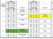
I followed the Excel sheet and it just took me 11 combinations to find the correct one!
Now it draw much less current compared to before (I do not run FULL throttle in this video):
[youtube]4u4bish1i8I[/youtube]
EDIT: updated video link to the correct one.
I think I can answer that now: Yes it does.
I followed the Excel sheet and it just took me 11 combinations to find the correct one!
Now it draw much less current compared to before (I do not run FULL throttle in this video):
[youtube]4u4bish1i8I[/youtube]
EDIT: updated video link to the correct one.
Attachments
eee291
100 kW
The gearing looks somewhat fast, no wonder it was overheating.
I feel the gearing needs to be increased for this power level.
I feel the gearing needs to be increased for this power level.
Okey. That is something that I really can not do anything about without major rebuilding.
What I can do is to put the original differential in reverse gear which makes it output an higher RPM.
These are the specifications of the differential. The DC-motor should output 580 RPM at 48V but now I run it in 60V. Do u think I should run the differential in reverse instead? Of course switching the phase wires to run the BLDC motor reverse also.
Please note that my BLDC motor has planetary gears which brings it down to 580 RPM.
Forward gear
Gear Ratio: 0.4225
Input: 580 RPM
Output: 245 RPM
Reverse gear
Gear Ratio: 0.5965
Input: 580 RPM
Output: 346 RPM
Still wondering about above.
But anyways… I am about to do the first real test runs on real roads this weekend.
* I have found correct hall/phase cable combo
* I run it at 60V
* I added 80A fuse at battery output
* I will add a current monitor display inside the cabin to be able to see how the current behaves while rest driving
* I will add a temperature sensor to the motor, but sadly not in the same enclosed area that the windings are in because they are hard to reach without dismantling the whole motor installation on the differential.
What more should I have in mind?
* check if phase cables get warm
* check if outer motor shell (aluminum) gets warm
How warm is OKEY?
Sorry I haven't replied, keep forgetting this open tab in the browser. too tired atm to process and reply usefully right now, but will leave it opne to recheck tomorrow.
Hey buddy, we all have those periods so no worries at all! You do not have to be sorry. I've been reading around on the forum and you share your knowledge everywhere. That is amazing! Thank you!amberwolf said:Sorry I haven't replied, keep forgetting this open tab in the browser. too tired atm to process and reply usefully right now, but will leave it opne to recheck tomorrow.
tndr_1 said:But anyways… I am about to do the first real test runs on real roads this weekend.
* I have found correct hall/phase cable combo
* I run it at 60V
* I added 80A fuse at battery output
* I will add a current monitor display inside the cabin to be able to see how the current behaves while rest driving
* I will add a temperature sensor to the motor, but sadly not in the same enclosed area that the windings are in because they are hard to reach without dismantling the whole motor installation on the differential.
What more should I have in mind?
* check if phase cables get warm
* check if outer motor shell (aluminum) gets warm
How warm is OKEY?
Sorry for hte long long delay....So: generally if a motor is getting towards boiling water temperatures, it's probably too hot (being overloaded in some way, or is at too high a load for the speed it is running (wrong gearing), wrong phase/hall combo, etc).
If the phase wires get hot, they're either too thin, or the above overloading/etc is occuring, drawing more phase current than should be necessary--controller itself will also typically get pretty hot in the wrong phase/hall combo scenario.
The best place for a sensor in the motor is at the windings, but if that's not possible, the next best is the casing that the windings are mounted to, at the point they are mounted there, where the least airflow occurs over it. (assuming the motor is an inrunner with the stator on the outside and the rotor on the shaft inside).
Depends on what you're trying to do. If you need to go faster for the same motor speed, the reverse gear would do that (assuming you can just change the motor controller to reverse mode) by the gearing ratio you have between F and R (346/245). Won't reduce the motor load, though (will go up because of faster speed needing more power).tndr_1 said:What I can do is to put the original differential in reverse gear which makes it output an higher RPM.
These are the specifications of the differential. The DC-motor should output 580 RPM at 48V but now I run it in 60V. Do u think I should run the differential in reverse instead? Of course switching the phase wires to run the BLDC motor reverse also.
Please note that my BLDC motor has planetary gears which brings it down to 580 RPM.
Forward gear
Gear Ratio: 0.4225
Input: 580 RPM
Output: 245 RPM
Reverse gear
Gear Ratio: 0.5965
Input: 580 RPM
Output: 346 RPM
If you're trying to reduce the load on the motor to prevent overheating, using the reverse gear to keep the same speed you already have should then reduce the load on the motor, I think. (am still tired from being sick, so certain things are hard for me to keep straight in my head ATM).
The idea is to let the motor spin faster for the same vehicle speed and same power requirement from the motor. It lets motor current drop, which means less motor heating from that.
Oh, also, if you haven't already done regular mechanical maintenance on the bearings and gearing of the drive system past the motor (diff/gearbox, axle bearings, etc) I'd recommend that. Bearings should all spin freely; if they don't they add to the load the motor must drive without doing anything for you. Same thing for the gearing--if grease or oil has aged or become contaminated, it may cause excess drag or wear on the gears (and their bearings).
Similar threads
- Replies
- 9
- Views
- 1,684
- Replies
- 3
- Views
- 1,598