Possibility of putting 66V through an MXUS DD rear hub?

monkeychops

100 W
Joined
Oct 17, 2011
Messages
160
Location
Wiltshire, United Kingdom
Hello all.

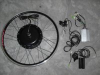
I have one of these:
dd_kit.JPG
from cellman.
It's a 500W MXUS Direct Drive hub (XF40 I think).

It's ace. Top speed is 25mph on the flat with 48V of lipos powering it.
Inevitably I want a few more mph in my pocket, for 'occasional use' on 'safe' roads. Only 2 - 3 more mph you understand ;)
I wondered about reconfiguring my batteries to output say 66V (I currently have 8 6S lipos giving 44V nominal).

So...... would 66V likely break my controller? Or break the motor? I don't have any significant hills on my usual commute. Would I need to open up the controller and see what the capacitors are rated at (or something like that?) Maybe buy an upgraded controller? Are they easy to swap in and out?
 
Take a look inside the controller first, as it's probable that the commutation capacitors may only be rated to 63V and also that the FETs may not be rated for much over 60V. If you can post the FET part numbers printed on the black plastic bit then it's easy to check to see what they'll take. The capacitor absolute maximum voltage will be printed on the can, the capacitors in question will be the largest ones inside the controller; some of the smaller ones will be working at a lower voltage as they'll be on one or more of the low voltage supply rails in the controller.
 
Motor no problem, but the controller would be likely to fry a capacitor, since they are likely to be only 63v max. So you'd only be 3v over at the end of the ride, but at the start of the ride you'd be about 10v over.

It might work, but you'd be taking a chance with the controller. You might want to just look for a cheapish ebay 72v controller if on a budget, or go for a lyens 12 fet controller if you have some cash.

Most likely a controller upgrade will also come with an amps increase, so you will have to be a lot more carefull about frying the motor if you go to 72v 40 amps. A lyens 9 fet 72v 20 amps controller will be safe, but seem sluggish compared to a 40 amp. You'd likely see between 30-33 mph on a 9 fet 72v 20 amps Lyens controller.
 
Thanks guys.
I'll have a look inside the controller. I suspect it's not up to the job.
So brushless controllers are more or less compatible with each other?
At the basic level: Battery wires and throttle wires into the controller, and hall sensor and power wires into the motor?
The cheapest Lyens controller is $80 without shipping costs (to the UK) :-(
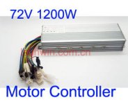
Something like this would do then? It says 33A.
72v controller.JPG
http://www.ebay.co.uk/itm/72V-1200W-Brushless-Motor-Speed-Controller-For-Electric-Bike-Bicycle-Ccooter-/251023036062
 
If you want the same controllers as Ed Lyen sells, but minus the customisations he adds, then look at getting one from e-crazyman (who supplies Ed Lyen with unmodded controllers anyway). The 72V one here: http://www.ebay.co.uk/itm/72V-1500W-brushless-controller-for-E-bike-scooter-/300705286217?pt=LH_DefaultDomain_0&hash=item46036e8849 will be programmable using the software around on this forum and there is a stack of knowledge here on tuning and tweaking these controllers.
 
I say if you already have the batteries, you can switch to 24S2P for 88V nominal and back to 12S if you wish.
I rode this exact cellman's motor at 24S for a while using his 12FET 4110 controller and it was a whole lot of fun!
It easily exceeded 40mph on flat and while the motor got pretty hot on longer rides, it never overheated.
Of course be careful if you go this route and encounter any serious ascents. Perhaps some kind of cooling mod would be nice.

Alternatively, 18S will get you to 30-35mph and you will get away with any cheapo ebay 72V controller made for 6 SLAs. But you would need one more brick to make a 3S3P battery. So 24S wouldn't be much more expensive.
 
miuan said:
I say if you already have the batteries, you can switch to 24S2P for 88V nominal and back to 12S if you wish.
I rode this exact cellman's motor at 24S for a while using his 12FET 4110 controller and it was a whole lot of fun!
It easily exceeded 40mph on flat and while the motor got pretty hot on longer rides, it never overheated.
Of course be careful if you go this route and encounter any serious ascents. Perhaps some kind of cooling mod would be nice.

Alternatively, 18S will get you to 30-35mph and you will get away with any cheapo ebay 72V controller made for 6 SLAs. But you would need one more brick to make a 3S3P battery. So 24S wouldn't be much more expensive.

Good to know the motor can handle this voltage.
Yes 3S3P was exactly what I was thinking, just need one more brick. There is *just* about space for 10x6S 4Ah Turnigy lipos inside my battery box.
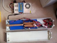
Here it is in the early days with just 4 lipos in it:
battbox.jpg

Lyens controller says 45A maximum. The cheaper eBay one said 33A which seems safer in terms of protecting the motor. I appreciate I could mod Lyens one but I'd rather have one that I don't have to program.
 
why don't you just open the controller and look? you keep throwing around these nominal voltages but they are not what the controller sees. you have to use the true DC voltage when the cell is charged to estimate whether the parts will work.
 
I will try and open up the controller later.
But how about this for an even simpler but potentially wrong idea:
Add in a couple of 3s lipos to boost the total pack voltage a bit?
This would take it to a total charged voltage of about 62v. or if that is too much, add in 2s instead to reach 58v. I'm only really after a few more mph.
I would buy the same make of lipos, same C rating, same capacity as the existing 6s lipos.
Would this work? Would the batteries discharge unevenly? Is this would work, it's the easiest solution.
At the moment I have 2 sets of 4 paralelled 6s lipos connected in series that give me 49.8V when charged, that makes sense.
 
if that is all you need, then you can see the caps when you remove the end plate and then you will know if they are 63V or 100V. you should be able to read the mosfets too without removing the controller pcb.

but before long one of the 6 packs is gonna blow out a pouch so you could just wait until then and cut down that pack to 2S on each side (4 pouches total + one spare) and use it like you are thinking. depends on how you charge. you would wanna stick to 14S if you had that kinda balance charger.
 
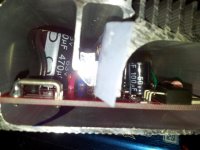
This is the best photo I can manage of the controller:
20121017_211729.jpg

I got the back off ok, but the front (where the wires come out) is reluctant to come.

So it says 63V on a large capacitor that I can see. And 50V on the small one on the right. So that proves I can't put more than 63V through the controller, right? But anything less would be ok? Or do I need to get to the FETs and check them as well. Not confident about opening up the controller any further without breaking something.
 
63 volt caps mean you can take 15s lipo, but thats pushing it to the bleeding edge. I run several of my controllers at that limit, I've never had a failure, but thats a lot like saying I've never lost at Russian Roulette.

As for the FETs, they can probably take it. if not, you'll know soon, and you were looking to replace the controller anyway.
 
So 14S should be ok then.
So if I buy a couple of 2S bricks and add them to my existing set of 10 x 6S bricks (12S2P), then that should be ok?
Next need to think about bulk charging. My MW clone only goes up to 53V. Easy to mod or looking like a new charger?
 
like i said, just wait for one of the packs to blow out a pouch and use it for the parts to make the 2 pieces of 2S, and then just buy a replacement for the 6S pack that blows out. it won't be that long. maybe some of the lipo guys can estimate how long.
 
A generic chinese 72V controller may cost you about $50-60 delivered. They can handle more power that the small controller you have now. Most have a 63V LVC which is perfect for 18S lipo (3.5V per cell is my preferred LVC voltage).
I would go this route also because your battery will be less complicated, and all balance plugs will be the same size.
Otherwise take a picture of the mosfets before you commit your 2S battery purchase/mod. Some fets in 36V controllers are really only good up to 50-55V. Also the linear voltage regulators may overheat at higher than rated voltages.

As for blowing the pouches, well I wouldn't wait. My 3yo Turnigys are still unpuffed and going strong, with only 1 out of 100 cells leaking voltage slightly.
 
monkeychops said:
So it says 63V on a large capacitor that I can see. And 50V on the small one on the right. So that proves I can't put more than 63V through the controller, right? But anything less would be ok? Or do I need to get to the FETs and check them as well. Not confident about opening up the controller any further without breaking something.

NO!!!

miuan has already said it, but it's worth repeating.

Just because the capacitors are rated at 63V doesn't mean that the controller is OK up to that voltage. There is a very strong probability that the FETs may be rated at only 60V, as these are common in lower voltage Chinese controllers. Also, the controller internal power supply will almost certainly use a dropper resistor to keep the first stage voltage regulator below its 40V absolute maximum differential voltage rating. This usually needs to be changed for one of a higher value if you're increasing the voltage significantly over that which the controller is normally rated at. The exception to this are controllers with a switched mode first stage regulator (the newer Xiechang controllers, for example), but your photo seems to show an ordinary linear regulator with the big dropper resistor behind, so I suspect there will be problems if you push the voltage up too high without some modifications.

[edited to clarify]
 
I hear what you are saying.
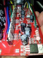
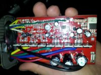
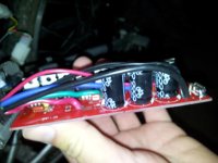
I managed to get the controller opened up this morning and hurriedly took some photos on my phone. Hopefully one of these shows enough information? Or can someone point out which component I need to zoom in on and look closer at?
20121018_090922.jpg
20121018_090905.jpg
20121018_090913.jpg
 
What we need is the number printed on the black part of the FETs, which is hidden behind the wires in the third photo. The FETs are the row of things sticking up down the middle, with copper tabs poking upwards. The type number will be etched into the black plastic on the front of them.

The power supply dropper resistor you have on that board is 180 ohm, which is too low for much over about 60V operation. Typically a controller, with throttle connected, draws an idle current of about 45 to 55mA, so the voltage dropped across this resistor will be around 8 to 10V. The absolute maximum input voltage of the first stage voltage regulator (the device marked "LM317K") is 40V plus the FET drive supply voltage of about 12V, so this means that, at the moment, your controller is only safe to about 60V to 62V. Changing the big resistor (the one with the brown, grey, brown bands) for one of the same size (normally around 2 to 3 W rating) with a value of 470 ohms would allow safe operation up to around 80 or 90V or so.

[edited to fix an error on my part]
 
Thanks for that, Jeremy. I will report back when I get home and have had a closer look at the FETs (now that I know where they are).

If the FETs look ok, then I can just replace that resistor with one you recommend and I should be good to go at 62V, or up to the maximum the FETs can take if that is lower than 62V? The resister swap looks like a fairly simple soldering job I could do.
 
Connect the controller power and measure voltage on all capacitors. It seems the smaller ones may only be rated at 50V. If any of them display the same voltage as the bigger ones (pack voltage), then you already have a problem going over 50V.
 
Will do that too, thanks miuan. The capacitors are all the black sticking up cylinders, right?

Note to self: be careful not to fry fingers and/or short anything on the controller when I'm doing this!
 
Just go order that 72v controller, from ecrazyman or whoever. Then keep that one as a spare for later if you need it.

Jeremy's comments put into technical reasoning why I've never recomended 15s lipo. 14s, charged to 4.2v is 58-59v.

My pings charge to 60v, but drop to 56 or lower with the first touch of throttle, so no problems so far using the pings. But you are talking about 18s lipo. The lvc of a typical 72v controller will still be low enough for you to run 18s. Mine, from cellman are set to 60v.
 
miuan said:
Connect the controller power and measure voltage on all capacitors. It seems the smaller ones may only be rated at 50V. If any of them display the same voltage as the bigger ones (pack voltage), then you already have a problem going over 50V.

Not going to be a problem here, as the 50V ones (if there are any) will be on the low voltage rails, either after the regulator or as bootstrap caps on the FET drivers, rather than on the main supply.

The main power rails in controllers stick to the edges of the board adjacent to the FETS, with all the lower voltage stuff grouped together in the centre or off to one side. As long as the big caps on their own outside the FETs are rated at 63V then you're marginally OK to go to 60V or so.
 
Thanks for your replies.
Haven't had a chance to check over the controller again yet.
But got to thinking about how I can add the 2x 2S cells into my pack.
I don't think it's going to work. I can't see how to arrange the lipos.
At the moment I have 2 sets of 4 x 4000mAH bricks. the 4 x 4000 bricks are paralleled together. then both sets are in series together to reach 48V.
I had in mind adding a 2S 4000mAH pack in series to each of these 4 x 4000 groups.
But from what I've read that won't work because each of the 4x4000 bricks have a capacity of 16Ah and this needs to match anything in series with it.
Is my logic right here?
So the only option is to upgrade from 48V to 72V, by buying one more 6S pack and arranging the 9 packs in a 3x3 fashion.
Correct?
 
there is no heat sink on your mosfets so you should be looking to buy a better controller anyway. those lipo shoulda already cooked that controller. kinda surprised to see it still intact.
 
Back
Top