Problem with GBK 36v bottle battery

tl01

1 mW
Joined
Oct 20, 2015
Messages
11
Location
Minneapolis, MN
About 6 weeks ago I purchased this kit --> http://www.greenbikekit.com/electri...g-e-bike-kit-with-samsung-bottle-battery.html

It's been on my bike, functioning mostly as expected for the past 4 weeks. The only oddity out of the box was that the indicator on the battery always had at least one red bar, but since range and performance were as expected, I didn't give it a second thought.

However, the battery stopped charging, and no longer powers the wheel.

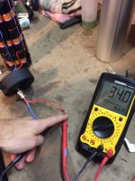
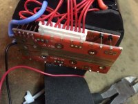
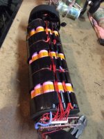
I opened the battery case to test voltage, and all of the cells that I'm able to easily access appear normal...so it seems like the problem is with the little gizmo at the top (shown in photos below...also, I'm a novice, can you tell?). The voltage on the other side of the gizmo is not the 36-38v that I would expect, but more like 12. Any good ideas on what a relative amateur might do to fix this? I already emailed GBK. No response just yet.
 

Attachments

  • IMG_0911.jpg
    IMG_0911.jpg
    48.4 KB · Views: 946
  • IMG_0910.jpg
    IMG_0910.jpg
    52.7 KB · Views: 946
More details:

I've been internet learning a bunch about batteries, and it seems that 10 wires to the bms gizmo would be most common, but there are 11. The voltage starts at 0 for the first wire and increments by ~4 for each for a total of 39.7v on the final pin...so obviously the battery is not bad. It seems like replacing the bms is the answer, but the 11 wire thing is throwing me off. What's the deal?
 
What you got there is 10S or 10 cell groups in series. Whatever series number you have will always need an extra wire to complete individual cell circuits for monitoring.

You could bypass the BMS and test cells (Toaster oven, space heater, large lamps, bike itself) to measure sag under load? Easier with a multi-channel volt meter. Try not to short between cell channels if using large meter probes. Rigging up clean connections for testing is imperative.
 
There's some things you can check before condemning the BMS. Disconnect and re-connect the multi-pin connector. if it's a 11 pin one, there's a fair chance that it'll reset the logic (if it has any). Next, if you can, check those cell voltages directly on the pcb rather than the connector to make sure all 10 sense wires are properly connected. Finally, check the voltage of the complete cell-pack between the red output wire and the thick one that joins the cell-pack to the BMS.

You measurements are a bit vague. Can we have exact values please?

Finally, The most likely culprit is the switch at the bottom of the case. Your BMS is very unusual for that type of battery. It's a normal BMS, but it's just that I have seen one like that on one of those batteries. Normally, they have a two-pin header on the top for the switch. How is your switch connected (if at all)? Assuming that it is connected, though I can't see any wires for it, can you check with your meter set to continuity directly on the connection points to the BMS to confirm that it is switching properly.

Your indicator LEDs are probably not related to the problem you have. The two wires are connected directly to the output wires. If only the red shows, you should at least measure the battery voltage to confirm that it reaches the normal 41.5V
 
Thanks for the help.

I tried unplugging and replugging the connector. No luck. One thing that I discovered is that when there isn't a load, the voltage is only slightly lower than normal. The attached photos document this. I connected an LED light and the voltage dropped to around 5v both before and after the switch, and the light was barely visible. With no load it's around 34.4v, and the switch seems to be working properly as the voltage either matches what is on the other side of the switch, or is zero when disengaged. If I connect the light to any of the cells on the other side of the BMS, it's perfectly bright. The voltages for the series are as follows:

0
3.9
7.9
11.9
15.9
19.9
23.9
27.9
31.9
35.8
39.7

I believe the battery was around half capacity or perhaps slightly higher last time I was able to charge it. Let me know if I'm not providing enough information. Doing my best with meager knowledge :)
 

Attachments

  • thumb_IMG_0913_1024.jpg
    thumb_IMG_0913_1024.jpg
    113.1 KB · Views: 898
On bottle batteries, the switch switches the BMS on?off, not the main power. Is your switch on the main power lines?

You cells appear to be healthy, which is good, because it's very difficult to repair them.

Your BMS is switched off. The only question is why? Did you check those cell voltages directly on the pcb? If not, check them again. If you check them again and they're the same, you then need to some checks on the BMS, but I think that won't be easy the way it's constructed with the components sandwiched between the two boards, so unless you're good at electronics repairs, it would be better to get a new BMS. You could bypass the output controls if it has a separate charge mosfet. The photo doesn't show enough to see whether it has a separate charge input. can you follow the wires from the charge jack to see where the negative goes to?
 
Thanks for the great tips.

It ended up being a bad connection between cells, which I was able to repair relatively easily. Great learning experience, and now I have an extra BMS.
 
Thanks for the resolution update! We’re often left wondering, WTF happened? LOL…

Yeah, it’s a bitch for my old, abused mind to keep track of multiple battery pack cell channels in the correct order for testing/rework. But, practice helps and every trouble-shooting job goes to improve our understanding.

You could also build a fresh pack with your extra BMS?
 
Glad it's sorted. Thanks for the update. It's really frustrating for other people searching for solutions for their problems, when they can't see why there was a problem and what fixed it.

Can you answer my questions about the switch and charging? Is the switch on the output line or does it switch the BMS? Does the charge socket have a separate negative to the BMS?
 
Back
Top