QSmotor/SiAecosys/Taizhou CT-22 Programming. 1 of 8

Hello Everyone,
Easy way to find out number of coils in electric motor is to connect classic voltmeter to its power lines and slowly turn wheel by 360 degrees counting numbers of movement of the needle (pointer). Just verified that way my 205 50H V3 QS Motor, has 16 coils.
Voltmeter was set to 3V DC scale. Movement of the needle very obvious.
 
Just discover another problem with my CT-22 display.
Wiring on the smaller connector, "B", is reversed between pins 3 and 4. Pin number 3 is connected to green wire, pin number 4 to black-green wire, just opposite to the diagram. So should I go by placement of the contacts, or by color of the wires? I'm afraid to power the display, not to damage it by wrong connection. Please advice.
 
Maciek said:
Just discover another problem with my CT-22 display.
Wiring on the smaller connector, "B", is reversed between pins 3 and 4. Pin number 3 is connected to green wire, pin number 4 to black-green wire, just opposite to the diagram. So should I go by placement of the contacts, or by color of the wires? I'm afraid to power the display, not to damage it by wrong connection. Please advice.

If the two grounds are not isolated from one another, it shouldn't matter which one you connect the GND from battery to!
 
I love reviving old threads. Got one of these CT-22's and mine is different for some reason. The number that gave me accurate speed was 0284 (in both 0xxxx and 1xxxx). 0xxxx changes the speed counting while 1xxxx changes the odometer counting. Why they are 2 different options I have no clue. This is for what I believe is a 2kw QS 10" hub driven by a sabvaton 96120 off the odometer line.

Also of note is in the settings menu I have a lot more options between F and R, and then a few more past R and before J. (J is still the end) No idea what they do.

Only issue I have is the clock is completely useless, I don't mind a 24hr clock, but I do think something is wrong here. [youtube]ifYq9qAF6Zk[/youtube]
 
marsrover said:
I love reviving old threads. Got one of these CT-22's and mine is different for some reason. The number that gave me accurate speed was 0284 (in both 0xxxx and 1xxxx). 0xxxx changes the speed counting while 1xxxx changes the odometer counting. Why they are 2 different options I have no clue. This is for what I believe is a 2kw QS 10" hub driven by a sabvaton 96120 off the odometer line.

Also of note is in the settings menu I have a lot more options between F and R, and then a few more past R and before J. (J is still the end) No idea what they do.

Only issue I have is the clock is completely useless, I don't mind a 24hr clock, but I do think something is wrong here. [youtube]ifYq9qAF6Zk[/youtube]

Damn... that is weird indeed! Have you connected the memory line of the display to battery +?
 
eVroomer said:
Damn... that is weird indeed! Have you connected the memory line of the display to battery +?

Yep. Followed the pinout exactly as shown earlier in this thread. It remembers all my other settings just fine, but the clock seems to run at the speed of lightning. My guess is a damaged clock crystal, but you would think that would affect the counting of pulses to set the speedometer too. You can set the clock and return to the main display without a reboot, so if it was a memory issue I would expect the fast clock to appear after a power cycle, but it starts immediately after setting the correct time.
 
marsrover said:
eVroomer said:
Damn... that is weird indeed! Have you connected the memory line of the display to battery +?

Yep. Followed the pinout exactly as shown earlier in this thread. It remembers all my other settings just fine, but the clock seems to run at the speed of lightning. My guess is a damaged clock crystal, but you would think that would affect the counting of pulses to set the speedometer too. You can set the clock and return to the main display without a reboot, so if it was a memory issue I would expect the fast clock to appear after a power cycle, but it starts immediately after setting the correct time.

I can't say I know much about clocks and how they operate, but it makes sense for something to not be working right! All other values displayed properly?
 
In this image from earlier in the thread
https://endless-sphere.com/forums/download/file.php?id=260220
U1 is a DS1302 which is a real-time-clock chip, and so the clock generally is not associated with other functions' timing, assuming your new version also uses this chip.

The most likely problem is something with the crystal (metal tube near chip) or one of the capacitors attached to the same pins. It could be the wrong one, or installed incorrectly. Is fixable in either case. Usually it'd be a 32.768khz crystal. Can't see the value in the pic above.
 
amberwolf said:
In this image from earlier in the thread
https://endless-sphere.com/forums/download/file.php?id=260220
U1 is a DS1302 which is a real-time-clock chip, and so the clock generally is not associated with other functions' timing, assuming your new version also uses this chip.

The most likely problem is something with the crystal (metal tube near chip) or one of the capacitors attached to the same pins. It could be the wrong one, or installed incorrectly. Is fixable in either case. Usually it'd be a 32.768khz crystal. Can't see the value in the pic above.

Good info. I'm trying to get QS to just send me a new one. But if they won't, I'll take it apart and look into this area of the board. Looks like it's large enough for me to hand solder just about any of those components.

EDIT: 4/14/2021, got tracking for a new one. Honestly surprised they sent anything. Didn't even have to go through the aliexpress complaint system, just normal messages. I was sad I'll have to put the miles on again from 0, but I think I'll just set the wheel math parameters intentionally wrong and spin up the wheel to put a few hundred miles on in a few minutes.

EDIT: 4/18/2021 Got a replacement, did a bench test, and it powers on and displays time correctly. Shoutout to QS for even sending a replacement, they could have easily just taken my money and run. I wouldn't have even been mad cause I'm not that hurt the clock didn't work right. Now I just gotta cut off the connectors and re-solder it all in.

EDIT: 4/20/2021
YUcz7fe.jpg

Old one that won't keep time. Everything looks good, I'm guessing a bad crystal. If I ever run across another in a dead electronic something I'll try to swap it. But I'm not spending money on fixing something I don't really care about at the moment. The new one installed easily and I found it tops out at 129mph, so it took a few hours to add my miles back on by just free spinning the motor. The trip counter also resets at 99.9mi. I only have ~50mi of range so that's not a problem for me, but it may be an issue for you.
 
20211217_163853.jpgHey all,

Sorry to revive, but im not smart enough to figure out the speedometer settings. Can snyone help out with the numbers?

I just installed the ct22 on my electric gokart, now need to set the parameters, I know how to get to it.
But i have no clue what numbers to enter for my tire..

Specs:

Qs Motor 138 90H 5 poles?
ASI BAC 4000 controller
Tires are 18x9.50-8
20s12p Sony VTC4 150a

Would really appreciate the help.16403201118582167949337783980248.jpg
 
I know this is a pretty big long shot, but I like the speedometer.

I have everything setup except the hall sensor and for the life of me can't figure out what kind of signal I need to send. My setup is completely different from anyone elses on here. I'm running a 72v system (DALY) into an Alltrax SR72400 motor controller that runs a dumb dc motor (ME1003). Neither the controller or motor have hall effect sensors built in for a speedometer.

I've been able to source a SSR41 hall effect sensor and wire it into the system (as well as the speedometer), reduced the Hz response of the speedomenter down to 1, but with no response from the speedometer. I've wired it up to my front wheel, like a bike speedometer.

Any help would be appreciated. If I can't make this work, Is there a different electric speedometer someone could recommend for my setup?
 
Well, I figured it out. I figured I'd put this post up so future me or future somebody could see what I'd done to make it work.

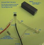
I sourced a A3144(unipolar), a 1K Ohm 1W resistor, and a white LED. I originally tested this on my bench with my dc power supply and 12 volts. I hooked positive to the positive terminal as well as to the resistor. I connected negative to the middle leg or ground. Then I connected the sensor leg to the cathode (or negative pole) of the led. Finally I connected the anode (or positive pole) of the led to the resistor. Bringing a magnet close (all I have are neodymium magnets, I could turn on the light, and turn it off by removing the magnet.

I then moved the entire piece over to my motorcycle. I created a quick connect for the hall effect sensor using automotive quick connects. On the other side I wired it up to the 12+ (black), 12- (green), and Sensor (Red/Black). Weirdly enough when wired in, the speedometer chose not to work. I wired up the light and resistor to see if I was having connection problems and then it started to work.

I'm still unsure why having a resistor and led wired on 12+ and Sensor allows the speedometer to work, but I'm not going to look a gift horse in the mouth. One other thing I noticed was that the led would dimly light when connected properly and then hit full brightness when activated by the magnet.

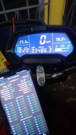
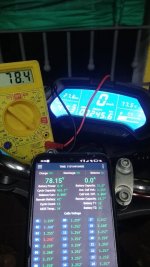
Afterward, it was just a simple test of what kind of Hz the speedometer was receiving. I calibrated it using a bike sensor (my primary speedometer at the moment, as well as my phone's gps sensor. Between the three I found that 10Hz was just about right (slightly under speed, by 0.5mph) for my setup. If I wanted to change the position of the sensor to be closer to the hub, or add more magnets, I probably could dial in the speed even more accurately than it is now. I'd have to increase the Hz, but would have better signal/noise ratio. (Something to think on.)

If anyone is interested in photos, I could probably produce them.

p.s. One final note is I noticed it really only starts going when operating at 10mph or higher. Any low speed maneuvers make the CT-22 unreliable and I need to rely on the bike sensor.
 

Attachments

  • hall_test-2238334765.jpg
    hall_test-2238334765.jpg
    109.6 KB · Views: 876
Aleria said:
I'm still unsure why having a resistor and led wired on 12+ and Sensor allows the speedometer to work, but I'm not going to look a gift horse in the mouth. One other thing I noticed was that the led would dimly light when connected properly and then hit full brightness when activated by the magnet.

Digital hall sensors like these typically have open-collector outputs. So they don't actually send any signals, they only ground the output when it's active. So if there is no pullup resistor to a voltage (like your LED and resistor), there's no signal changing from one voltage to another during operation.


p.s. One final note is I noticed it really only starts going when operating at 10mph or higher. Any low speed maneuvers make the CT-22 unreliable and I need to rely on the bike sensor.
If you can change the number of poles in the CT-22, then you can use many more magnets on the wheel speedo sensor and it will pulse more often even at low speed. Using 10 times as many magnets (and setting that many in the CT) would mean it would operate down to 1mph. In theory, anyway, assuming the reason for the problem is simply insufficient resolution.
 
Bumping an old thread. I am hoping to use this cluster on my golf cart. My motor controller setup is similar to Aleria, so I need an external hall sensor. I purchased the hall sensor below. With the cluster and hall sensor hooked up I am not getting any reading on the cluster. I also added up a pull up resistor with no luck. I am testing by moving the magnet in front of the sensor repeatedly. The LED illuminates on the sensor when near the magnet. Any input or advice would be appreciated! Thanks in advance!

Twidec/10mm Hall Effect Proximity Sensor Inductive Switch NPN NO(Normally Open) with Magnet DC5-30V NJK-5002C https://a.co/d/cEVJRex
 
Try mounting the magnet on something you can rapidly spin past the sensor, or even multiple magnets. It seems per previous posts that the resolution of the display's response is not very high, so it may take many pulses in a short time to get it to respond.
 
Hello guys,

This thread is a gem. Its been very helpful for me.

I have both DKD and old CT22 display. The reason im using DKD is due to my battery pack (LiFePo4). I've been able to ajust battery bar offsets to make it as linear as possible.

My lifepo4 72v nominal battery pack:
100% = 79.2v
80% = 79v
60% = 78.4v
40% = 78v
20% = 77.6v

Now the issue I haveis to figure out how about "battery judgement time" J-xxxx. My display has one more setting "H-xxxx" that seems to be also related to battery judgement. The problem is due to voltage sag, sometimes bars goes down more than it should and dont go up again
 
If voltage will rise, you need J-xxxx time to remember new value. If voltage will drop before J-xxxx time expire, bargraph will immediately return to previous position.

If voltage will drop, you need C-xxxx time for the bar graph fall from full power to zero. Or C-xxxx time / 10 for each point.

So, if you have frequent and long voltage drops, you need shorter J-xxxx time and longer C-xxxx time.
 
vlad_vy said:
If voltage will rise, you need J-xxxx time to remember new value. If voltage will drop before J-xxxx time expire, bargraph will immediately return to previous position.

If voltage will drop, you need C-xxxx time for the bar graph fall from full power to zero. Or C-xxxx time / 10 for each point.

So, if you have frequent and long voltage drops, you need shorter J-xxxx time and longer C-xxxx time.

Thanks for repply. It seems the bars energy never goes up like another displays, right? unless I turn off/on the display.

Im going to test the J-xxxx and C-xxxx parameters as you stated. My current settings for those are J-0120 (120s seems to be the maximum for J param) and C-0300 (default value)

The main problem os the battery bar is such thing as judgement time and bars never goes up... this makes things hard for LiFePo4 battery packs with considerable voltage sag.

ALSO: there are unkown parameters such as H-xxxx and L-xxxx

---- UPDATE -----
lowering Judgment (J-xxxx) only made the things worse, now almost instantly battery bar lowered to half when it was supposed to be 90%. Lower the J param, faster bar follow the voltage sag and bargraph will be much lower than it should

increased Coulomb param: C-0300 to C-0600, display accepted the new value but noticed any change on display behaviour
 
When running, the display grid only drops and does not rise. Whether it should fall or not, the judgment time is 30 seconds, and the falling speed is 15 seconds per block.

Now I see that the bargarph newer rise, but after display reboot only. You can try to set discharge voltage levels with voltage sag. And return J and C to defaults.

Oclipper said:
ALSO: there are unknown parameters such as H-xxxx and L-xxxx

I think they related to voltage change rate.
If the voltage change exceeds the value set by the power change rate, the pointer is updated to the new value after the time is greater than the maximum time, otherwise the current position remains unchanged; if the voltage change is less than the value set by the power change rate, the pointer is directly updated to the new value.
 
Hello guys,

Im having trouble with my "NEW" Ct22 speedometer. Its is showing 0,5 to 1 Volt lower than it should. Ive already checked bms, controller, wiring harness, connectors... My "OLD" Ct22 shows voltage correctly (older model is that with lower brightness/visibility). Is there something I can do in order to adjust voltage accuracy?

PS: I use LiFePO4 battery, even 1 volt makes a HUGE difference.
 

Attachments

  • -8948658311719306144.jpg
    -8948658311719306144.jpg
    158.4 KB · Views: 118
  • -894869285-2076504044.jpg
    -894869285-2076504044.jpg
    161.5 KB · Views: 118
If none of the programming parameters available are for adjusting the readout, then you could adjust the resistor voltage divider it almost certainly has, between the input voltage (main power, probably), and one of the chips on the board. The voltage divider will have one resistor in series with the input voltage and the chip, and a second from that point to ground. The series resistor will likely be a lot higher (several times) the value of the second one. The point where they connect will have a scaled down version of the main input voltage, to prevent damage to the MCU; this will vary with the input voltage proportionally to the resistor ratio.

So you could change either of the resistors to a small multiturn potentiometer of slightly higher resistance overall, then adjust the pot slowly and carefully while watching the voltage display to calibrate the readout to match your other meters.

When looking for the divider, there may be a small chip with a few pins between it and the main bigger chip. It's good design to have a buffer op-amp (usually a small few-pinned chip) between the MCU and the divider, but they could've left that out for cost or simplicity (just leaves it more vulnerable to MCU damage by overvoltage on the input pin). So the divider could go directly into either the smaller STM chip or into the larger main chip.
 
amberwolf said:
Try mounting the magnet on something you can rapidly spin past the sensor, or even multiple magnets. It seems per previous posts that the resolution of the display's response is not very high, so it may take many pulses in a short time to get it to respond.

Finally got around to trying to get the speedo to function. I mounted up a arm with the magnet on my drill press and no luck. With the hall sensor hooked up to 12v + and - the output reads 10.7v with no magnet and once the magnet is over the sensor is pulls down to 0v. When the signal is hooked up the speedo it reads around 6v with no magnet and zero with a magnet. Anything to try or input would be greatly appreciated!

EDIT: I ordered a signal generator to verify the speedo was not defective. It worked. I readjusted the settings on the speedo, hooked up the hall sensor and it worked! Not sure what I was doing wrong. Thanks for the help!
 
Back
Top