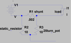
shunt mod via a voltage divider

nebriancent no worry about stepping on anyone... the more folks doing great things with electricity the better. Everyone that contributes brings a bit different perspective, and adds to the community. So keep up the good work!!

Wurly, this mod would only allow you to increase the current from stock. To decrease the current you would have to replace the shunt with one with higher resistance, or decrease the number of shunts in parallel.

The basic principal is that the micro reads the voltage generated across the shunt which represents battery current draw according to ohms law E = I/Rshunt Say we are generating 0.100 volts at the "trip point" where the micro takes action to dial down performance. What we are adding is a voltage divider that divides down the 0.100 voltage. Say we want to double current draw, then we would divide the shunt generated voltage by 2 by setting our 10 ohm pot right in the center.

Hope this helps. The thread mentioned above has a representative schematic hack and the equation of state.

http://endless-sphere.com/forums/viewtopic.php?f=2&t=31643
 
I understand bigmoose,thanks for the reply, maybe i should have added more to my post. Yes i was thinking, instead of adding solder to push the current limit higher, reduce material in the shunt or replace(higher resistance) and add a trimmer (pd network) to tune the limit to my battery requirements.
It's the 'trip point/microprocessor action' you mention that i'm interested in. Does it shutdown or dial down performance? :?
I have an analylog circuit i designed using op-amps. The voltdrop across an additional remote shunt is amplified (gain 200)through the opamp and a threshold is set with a pot to another opamp which goes high/low switching a transistor to clamp the throttle signal. It works ok but is a bit on/off pulsing which can be annoying. I was looking for another solution and wondered if the controller current sensing could be modded to do the same thing only more effectively...read smoother.
(Sorry for hijacking the thread)
 
Wurly, have a look at what the Speedict can do. You can download the latest manual from theire website - all 60 pages, It has current limiting, softstart, and coming soon is throttle profile, If you haven't already got an Android phone, you can get a cheap one from Ebay and just use it as a cycle computer.
 
d8veh said:
Wurly, have a look at what the Speedict can do.
Or you could just use the CA :)
The current version has the hook for adding a few resistors and switches to get multiple power limits. See section 9.2 of the manual - works great.

d8veh said:
...and coming soon is throttle profile...
Coincidence is a wonderful thing... :lol:

justin_le said:
Sun Apr 01, 2012 11:55 am
Re: Cycle Analyst V3 preview and first beta release
...throttle mapping concepts... I'm going to give some thought about the best way to implement this ... and will try to get it in the next firmware update to test out.
speedict said:
Wed Apr 04, 2012 6:23 am
Re: Speedict Ebike - Anybody seen/tried this?
...by the way we have plan to design customize power band...
 
bigmoose said:
The basic principal is that the micro reads the voltage generated across the shunt which represents battery current draw according to ohms law E = I/Rshunt Say we are generating 0.100 volts at the "trip point" where the micro takes action to dial down performance. What we are adding is a voltage divider that divides down the 0.100 voltage. Say we want to double current draw, then we would divide the shunt generated voltage by 2 by setting our 10 ohm pot right in the center.
i accualy used a 10 ohm resistor on one side and a 10 ohm pot on the other so it will sweep from 1x to 2x current draw and wont go into a no limit mode
Screenshot-1.png
 
btw i also use a ca to turn down the output to the hub if i want too but the thing i love about my mod is it is reversible by zeroing out the pot ... or i could go over 2x by changing the the pot with lets say a 20 ohm pot bringing the current limit from 1x to 3x available current with a simple twist of the pot

and big moose i came to the same conclusion that the controller was looking for 100mv to start limiting judging from the resistor value and the current i was able to pull from the controller i was able to simply use ohms law to find this out

if a person wanted a lower output from the controller they could easily send the signal trough a opamp first and then have a voltage divider on the output to give you a under-over clock capability through though the voltage divider
 
Wurly said:
Does it shutdown or dial down performance? :?
at 100mv read from the shunt it doesn't shut-down but instead it alters the pwm (pulse width modulation) to limit the available current from the source much like a smpsu(switch mode power supply) dose with pfc(power factor correction)

and don't worry about the potential hijack the idea is related to this mod and should be brought up

for explanation as to the current limiting being under-clocked see my last post
 
Thanks nebriancent
Great information there.
I'll take the cover off my controller and see if i can find the track from the the shunt to the microprocessor. I like the opamp idea. If over/under clocking can work this way, it's a good low cost solution making sure batteries don't exceed their C rate or for those who want to 'pep' up the performance.
D8veh, i also like the speedict solution but i'm looking at ways of current limiting mods on many controllers not just my bike.
 
just look for a small trace running from the high side of the shunt (load side ..not battery side) to a small ic

should be the only small trace on the PCB running from the high side of the shunt

that's the signal you will want to modify

from what I cam tell its the same thing on the golden controllers aswell ..... it looks for 100mv (0.1Vdc) before the limitting starts

if you want I could in my spare time make a simple over - under current mod using a opamp a pot and a copper of resistors and post it
that being said I don't know when I will have time for it as I still need to finish my ballancer and post the scimatics and pics on another thread
let me know iether way
 
I have been busy with one of my controllers. It's a 36V 15A from evassemble, not sure who manufacturers it. I have found the track and made a cut. There is an 8pin IC to the left which i presume is a signal conditioner (opamp?) for the shunt reference voltage (pin7)to the micro.
I have added 3wires, green to a 1k smt resistor and white black to either side of the shunt. I will play with increasing the resistance of the shunt resistor tomorrow and see what happens to the controller as it tries current limiting. When my trimmers arrive i can then increase the limit to the desired amount.
The next thing is to add the opamp for under/over adjustment. I presume the wiring of the opamp would be as a voltage follower and potential divider on the output? My knowledge isn't great with circuit design so i would appreciate your ideas for the circuit. I can build it no problem.
If this works i can add the mod to higher powered controllers.

SDC13212.jpg
 
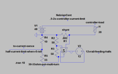
not as a follower but as a amplifyer... taking the signal and adding a multiplier to trigger the current limit early... the have a vd on the output to have a over-under clock mode

under-clocking is set by the negative feedback to the op-amp and if 1/2 of current limit isn't low enough use a different resistor network for the feedback control

remember that when r5 =0 current limit is.5 of the controllers stock limit
r5=10 current limit is stock
r5=30 current limit is x2

new current limit.png
 
this clear anything up?
 
for clarity the only parts that are new to the controller are r2-5 and u1

r2-4 use 1/4w resistors as they will have a little better lead strength
r5 i would use a 10 turn pot smt would be fine unless you want your limit adjustable from outside the controller

WARNING IF THE OUTPUT OF THIS CIRCUIT BECOMES DISCONNECTED FROM THE CURRENT SENSING PART OF THE CONTROLLER YOU CURRENT LIMIT BECOMES INFINITE

WARNING 2 MAKE SURE IF YOU HAVE THE CURRENT OUTPUT MULTIPLIED THAT THE OTHER COMPONENTS WILL TAKE THE STRAIN (BEEFED UP POWER LEADS,HEAVER BATTERY CABLES, C-RATING OF BATTERY IS NOT EXCEEDED, POWER MOSFETS ARE NOT OVERWORKED

***EDIT only 5 parts used in this circuit making it a affordable mod

for a under-clock to stock mod replace r5 with a 10 Ohm pot
 
uploading the spice modle for this circuit so you can play with it a bit and change it to your liking

program to view edit and simulate

http://www.linear.com/designtools/software/#LTspice

spice file


remove the .doc extension to open it in ltspice

to see what is happening in this circuit meter the voltage on the high side of the shunt .... then the output of the op-amp.... then the output of the voltage divider

for a less then 1/2 of stock current limit decrease r2 or increase r3 in resistance
to set your under over sweep adjust r5
remember that once the controller reads .1v (100mv) is starts to limit
so if you output voltage from the voltage divider is 2x the input from the high side of the shunt you will lower the current limit to 1/2 of the stock value
if your output voltage from the voltage divider is 1/2 of the input from the high side of the shunt your controller will have 2x the current limit
if your output voltage is the same as the input the controller will limit as if it was stock


**EDIT

i submit this circuit to the community as a open source design and it can be redistributed changed modified in any way the end user and or community feels fit providing they at least reference my original design

i would hope that those that attempt this mod understand what it dose and how it works before doing so because if not understood or if wired wrong it could turn you beloved e machine into a expensive lawn ornament

i would love some input on this design from the doc or big moose or amberwolf... basicly anyone with any valid input would be appreciated
 
Nice work Nebriancent, and thanks for explaining all of the details down to a level that an electronics simpleton like me can understand. Ending the need for programmable controllers with a change that gives us the ability to make changes even on the fly is a great equalizer.

:idea: Now for your next project...How about something just as simple and cheap that changes our bargain controllers to sinus output?
 
nebriancent said:
this clear anything up?

It certainly does. Thank you for taking the time to draw a schematic.

For my own benefit had a play around with that old controller this weekend, by increasing the resistance of the shunt i got the current limit down from 18A to 9A just to see how the controller behaves. Limiting starts from 50mV and i never saw a reading above 72mV. It will not reduce the pwm to lessen the current draw below 9A, but thats ok, i wouldn't want it any less anyway.
When i get a chance i'll build a circuit to make Vref adjustable.
 
one thing should be noted .... by increasing the shunts resistance you have made it drop more voltage for any given amperage so in effect have asked it to dissapate more heat per amp of draw through it

now that I have come to the realization of how easy it can be to turn down the controller with a handfull of descreet components I think my next controller mod will involve hard nodding the shunt to the max current I want from the controller then using the above circuit I scetched up for you to turn it back down if needed

my Shintom is currently being asked to shed 20 watts of heat (breifly off the line)
I could get a small amount more voltage to said motor by lowering the value of my shunt
or..... I could go for a insane shunt value so that I drop next to nothing in voltage and create next to no heat and just have the max sweep set to what I think is a safe(ish) current limit and have it drop from there....

thankyou wurly I have learned somthing by helping you out with your current underclock request

mabee I even learned more then you by showing you how it could be done
 
one thing occurred to me

i could use this same design to modify a meenwell to drop its current (the op amp/vd) just a thought... ideas?
 
I'm trying to do this mod to a non-programmable controller that I specifically ordered with a low current limit, so I could end up with a controller that I can vary from modest current to extreme. My problem is that there is no trace going from the + side of the shunt to the controller brain. The brain connects to the negative side and battery neg comes in there. The closest thing I can find is a thin trace that comes off of the beefed up main trace to which the positive side of the shunt is connected, but that trace goes to a 3500 ohm resistor before going to the controller brain.

Does that make sense as the correct trace to cut? I was thinking the feed for the current sense was a direct trace to the brain. I wanted to be sure before I go hacking through a trace that I can't repair. If it is correct then the mod is especially easy, since there's an open pin connecting to the trace just before the 3.5k resistor, making the mod only cutting the trace and soldering that even my caveman skills can handle.

John
 
John in CR said:
I'm trying to do this mod to a non-programmable controller that I specifically ordered with a low current limit, so I could end up with a controller that I can vary from modest current to extreme. My problem is that there is no trace going from the + side of the shunt to the controller brain. The brain connects to the negative side and battery neg comes in there. The closest thing I can find is a thin trace that comes off of the beefed up main trace to which the positive side of the shunt is connected, but that trace goes to a 3500 ohm resistor before going to the controller brain.

Does that make sense as the correct trace to cut? I was thinking the feed for the current sense was a direct trace to the brain. I wanted to be sure before I go hacking through a trace that I can't repair. If it is correct then the mod is especially easy, since there's an open pin connecting to the trace just before the 3.5k resistor, making the mod only cutting the trace and soldering that even my caveman skills can handle.

John

What controller is it? If it's one from Wuxi (i.e. KU series, Greentime, Hua Tong etc) then there is a mod I posted here: http://endless-sphere.com/forums/viewtopic.php?f=2&t=44277&start=15#p645302 that might help. It gives an adjustable current battery limit to these controllers over a range set by the value of the added resistor/pot combination, without interfering with the fault protection circuit.
 
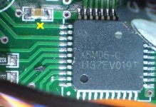
Thanks Jeremy. I like your method because it's a bit easier and doesn't involve cutting the trace. In your other thread it mentions tying the partial bypass to pin# 9, but I searched and couldn't find a data sheet for this MCU or anything saying where the starting point is for pin# 1 on a square 44 pin chip like this to confirm which is pin# 9. It's a Greentime 24fet controller and here's a pic of the MCU. I put a yellow "X" on what I think is #9 and is the trace going to the resistor and on to the power trace that connects to the positive side of the shunt, which I talked about doing the low resistance partial bypass before the resistor in my previous post.

John

edit- oops, forgot the pic now edited too
2nd edit- I double checked and my X was in the wrong place and no way I can interpret it as being pin# 9. It's the top pin on that left side. Resistance between it an the positive side of the shunt is 3.35kohms.
24fet MCU Leo controller.JPG
 
This will help you with the pinouts. I found it in another thread.

http://www.avdweb.nl/Article_files/Solarbike/Motor-controller/China-BLDC-motor-controller-36V-250W.pdf
 
Wurly said:
This will help you with the pinouts. I found it in another thread.

http://www.avdweb.nl/Article_files/Solarbike/Motor-controller/China-BLDC-motor-controller-36V-250W.pdf

That schematic agrees with Jeremy's mod in the thread he linked. Your avdweb link even had a small tuning of the current via pin#9. I take it that the MCU's can be programmed differently. My pin#9 according to the same lettering stamp of the part# has on 200ohms between pin#9 and the same trace going to the + side of the shunt. Pin#10 has 1.8kohms and #11 goes to ground.
 
Sorry for being late back to this, we had a power cut last night. Looks like you have it cracked now.

The settings for controllers using the X8M06-C can be programmed by the dealers, in the same way as the Xiechang ("Infineon", Lyen, e-crazyman etc) controllers, using the serial port connections that are shown on that schematic. Unfortunately the people selling the Wuxi (Hua Tong/Greentime/KU series) controllers won't release either the programming protocol (which would probably allow the XPD programming software to work with them) or the programming software they use. I suspect that the programming protocol will be fairly similar to that used by the Xiechang controller, but without access to the code we can't begin to guess what it might be.
 
I tried the mods suggested by nebriancent a few months back. I must have got something wrong with my circuit because when i open the throttle the battery BMS shut everything down. Whoops!!
After that i restored everything and set current limit by altering the shunt resistance.
For me, i'm interested in reducing as well as increasing current levels to keep within my batteries C discharge rating and also for range.

Question for Jeremy.
Am i correct in thinking that by adding a pot in parallel with r45 (2k) i can reduce the current limit?
This way i can reduce current by adjusting one pot, and increase current by another pot (using your mod)
 
Back
Top