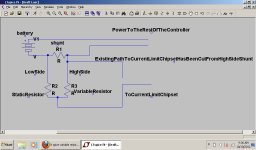
shunt mod via a voltage divider

Wurly said:
Am i correct in thinking that by adding a pot in parallel with r45 (2k) i can reduce the current limit?
This way i can reduce current by adjusting one pot, and increase current by another pot (using your mod)

Yes, reducing the value of R45 will reduce the battery current limit, but it's already pretty low, just 12 A as standard, so would you really want to decrease it below that figure?

If you wanted to increase the adjustment range then just use a fixed resistor across R45 to reduce the value (and hence battery current limit) and then use the new pot to gain a wider range of adjustment.
 
On mine, since I'm unclear on which is the correct direction for current limiting at the fork in the trace, one with about 2kohms and the other 3.3kohms between the shunt and the pin, I'm going with the low resistance partial and variable bypass that I'll attach before the fork and resistors. Since I can only find that single trace from the + side of the shunt (though at that main trace coming from the FETs), I'm confident that is the right place. It even gives me an open pin for connecting, so I just cut the trace and have easy soldering to do.

The one thing I'll do differently is use only resistors and a 3 way switch. eg put a 20ohm in place of the trace I cut and the bypass from the negative side of the shunt will have open circuit = programmed current , a 20ohm route = double programmed current, and a 10ohm route = triple the programmed limit. 50/100/150A battery side. I'll experiment first, but that gives you an idea. With hard wired resistors, I think it gives me protection from any possibility of a failure resulting in an unlimited current situation as long as I put the resistors for the bypass on the MCU side of the switch.
 
@ Wurly

if you have the voltage devider set up backwards or without the resistor in then it is posable to have no limit on your controller

sorry for taking awile to get back to this thread i have been bussy with life

i have been running the shunt mod since i first posted pics and have had no ill side effects as of yet
although i did also beef up my traces, made sure my caps, power resistors, and mosfets were up for the chalange


im sory to hear that your mod went bad if there is anything i can do to help youguys out that are still struggling with it just let me know
 
shunt reexplained.jpg

if r3 = 0ohm (but is still connected) stock controller operation is enabled
if r3 = the same as r2 then controller current is doubled
using a pot as r3 allows for anything inbetween
r3 could be subbed in with a multi-switch connecting various resisters in its place and or creating a short across r3 for the same results but with predefined limits
 
I’m a little confused by this thread. With the 6FET schematic I have in hand, R45 goes to +5V and the other end goes to C2. Are we trying to manipulate C2 input to the MCU?

I have modeled this in Spice and: At 48V with a 20A load, C2 = 185mV. (The value is relatively unchanged for 63V.)

Are we trying to drive C2 into the GND for more current, and raise it towards +5V for less?

If so, what are the safe targets for both?

Example, less say I want a range of ¼ power to 2X (presuming either limit doesn’t melt the Shunt solder or pop caps and fries FETs). :wink:

Intrigued, KF
 
all i am doing here is taking the voltage drop across the shunt that is read by the mcu and building a voltage devider around it to make the mcu not recognize that it has infact reached its current limit until a predetumend limit set by said voltage devider

example


shunt =1ohm (for simplicity) for every amp we feed throug it the shunt drops 1 volt
so for example if you have a 100v system drawing 1 amp through a 1ohm resistor on the neg side of the circuit the high side of the shunt would read 1v
for the same setup drawing 2 amps the high side of the shunt would be at 2v
so by taking the vfoltage sencing wire and running thoug a voltage devider we can have 1v seen at 2 amps and so on

the acual value of the shunt is a lot lower then 1 ohm
and the target voltage across the shunt before the controler cuts out is comanly 0.07v - 0.1v but the princable works the same
 
but in responce to your question KF.. simple answer for my own work here .....no i am not touching anything at all exept for the shunts voltage drop itself
after that the mcu and all other curcuits can do what it will with the analog information it recives

what i was after is a way to alter the current limit of ANY controller without needing to know how the signal is prosessed from controller to controller
and from what i can tell i have been successfull

i have modifyed ecobike, infineon, clyte, and golden controllers with the methods i have outlined above and have had no unexpected outcome from any controller i have modded in this way

i have also used this to mod power supplies aswell and it seems to work well

the voltage doubler curcuit i already posted works well on turning things down that have their current limited by a mcu reading shunt voltage drop aswell

i infact used a combo on a lab supply that i built for a buddy that had a stock unsetable current limit that would drop voltage to maintain cc operation
 
Right. Well, I’ve taken your last circuit and pasted in the missing components that feed the MCU. See attached LTSpice file.

View attachment ControllerCurrentLimitV3.zip

The circuit you’ve designed has no effect on C2, only the Shunt. So it’s a hardware mod against the Shunt, not against the MCU. (no disrespect) :)

I would be more inclined to dabble with spoofing the MCU and leave the shunt(s) as is – unless your boards are limited by the shunt value. I have plenty of power, so I don’t need to butter up shunts. I am more keen on how to vary the power on the fly during Brake/Regen. If I can attach to the leg that affects the MCU selectively at a time of choosing with a value of my own – and leave the rest alone for normal operation, then I’ve done my job. :wink:

Wurly/Jeremy say in a previous quote:
“…reducing the value of R45 will reduce the battery current limit…”
As such, I am tempted to stick a pin there between R45 and C2 and twiddle to affect the MCU directly without additional hardware (sans what I have to create proposed effects).

Make sense? :)
~KF
 
I would be more inclined to dabble with spoofing the MCU and leave the shunt(s) as is – unless your boards are limited by the shunt value. I have plenty of power, so I don’t need to butter up shunts. I am more keen on how to vary the power on the fly during Brake/Regen. If I can attach to the leg that affects the MCU selectively at a time of choosing with a value of my own – and leave the rest alone for normal operation, then I’ve done my job. :wink:

I’m not hacking the shunts value (resistors in use are way to big for that to effect the overall value of the shunt in parallel in as real meaningfull way)... just hacking the output for the voltage dropped over it in a way that is easy to do and should work on anything that uses a shunt to measure current for protection so i can make said protection trigger earlier or later (higher or lower max current)


once the shunts voltage drop exceeds 100mv the mcu sees this and puts the controller into a different pwm duty cycle
and for re-gen it is the same once the voltage drop over the shunt exceeds 40-50mv it changes to pwm for the re-gen (if i understand it right--feel free to correct me on the re-gen side if i have misunderstood it as i have gained this theory to explain what i have seen)

i mean no disrespect to you KF but i find hacking the mcu is just not necessary
i find it unimportant how the signal is conditioned after the shunt to read current as it seems to be different in every controller i have opened so if i can take the one constant (there is a voltage drop over the shunt and said drop will be measured) and modify it i can have something that will work on everything

for a easy way to boost just the Regen .. i have thought that through already


same circuit you modified with my scrap of rat droppings circuit feeding the mcu signal conditioner using twice as many amps and having a close to the same output to the mcu
 
you could use a relay to switch internally weather or not it will use my circuit to feed the stock one
 
“Ah... I see” said the blind man, though he could not speak. :wink:

For L1, use “PULSE(5 50 1 4)” and we can observe C2 rise from 151mV to 192mV. I might take the plunge and monitor that leg between 0-100% Throttle, and when in Brake mode to characterize it so as to perhaps create an immutable control.

At present I happen to have a control circuit already built that was used to study and manipulate UV for Brake, but the Controller is being fickle and samples but once during the braking event. If C2 is read dynamically and iteratively, and if the value can be manipulated during braking – I only need to move one wire, the same wire presently attached to UV to modulate C2 from the dash.

The part I do like about your approach is that it appears to be voltage agnostic: That simplifies things greatly. :)

Your work is timely & I thank you, KF
 
i do see what you are trying to do and i found it overly complicated and unnecessary .. not to say
i don’t respect the effort being put in as it looks considerable
i figure to just keep it simple and there is less that can and or will go wrong (for myself) i have
spent far to long trying to spice things only to have them burn anyways

i fear your hack may be more specific to exact hardware layout, brand, and revision of the
controller you are working on

most controllers seem to vary a Little when it comes to signal conditioning of the shunt voltage
drop so i just avoided hacking the built in conditioner and went strait for the source
 
View attachment ControllerCurrentLimitOnRegen.asc.zip
View attachment 1one thing i have just noticed is it seems that the regen current would be almost unlimited with the circuit turned on :O (not taking into consideratoin battery voltage, ir of batteries, kv of motor, losses through wiring, and bikes current speed)

although the first voltage hack i did would work fine to only double Regen current

voltage divider circuit has twice the Regen current but output seems very close

i would maybe for arguments sake have the line switched by a small dpdt relay off of the Regen lever (would make keeping brake signal and current signal isolated simple) and have your lever switch current modes on the fly as you brake to a predetermined value you have set as a multiplier for Regen

i myself have found 2x Regen awesome but still find myself wanting more but.. i also find that i cant reach 20 something amps Regen unless i am travelling fast enough
 
John in CR said:
Thanks Jeremy. I like your method because it's a bit easier and doesn't involve cutting the trace. In your other thread it mentions tying the partial bypass to pin# 9, but I searched and couldn't find a data sheet for this MCU or anything saying where the starting point is for pin# 1 on a square 44 pin chip like this to confirm which is pin# 9. It's a Greentime 24fet controller and here's a pic of the MCU. I put a yellow "X" on what I think is #9 and is the trace going to the resistor and on to the power trace that connects to the positive side of the shunt, which I talked about doing the low resistance partial bypass before the resistor in my previous post.

John

edit- oops, forgot the pic now edited too
2nd edit- I double checked and my X was in the wrong place and no way I can interpret it as being pin# 9. It's the top pin on that left side. Resistance between it an the positive side of the shunt is 3.35kohms.

pin one is maked by the indent (dot) in the chipset and the dot on the board and you count up the numbers in a counter clockwias fashion
by the looks of it it would seem you have identifyed pin 34
 
Back
Top