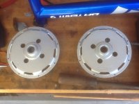
Side cover mod, now motor problem. HELP

Obiwan007

1 kW
Joined
Dec 16, 2012
Messages
332
Location
Northern California
So, finished my side cover venting project and it turned out pretty nice (pics comming). Problem now is that the motor is running funky. It is real jerky and and won't run smooth. A first I thought one of my phase wires had come loose, but no all are properly connected. So then I'm thinking hall wire problem. I had to take the blades out of the male side of the connector to unthread it from my frame during the upgrade. I carefully marked each wire and each socket when I did this though so I could be sure to get it back together all the same. So, I am pretty sure the halls are all in the right order. Any advice? I want to go back to using the Electric Jeepster as my commuter but right now I'm stumped. Please help!
 
One of the hall spades may not be sliding in correctly. Are they all locked in? I've also see one slide off to the side of the connector instead of into it's slot.
 
It does sound like a wiring problem. Either you mixed them up, or got reconnected funky.
 
Ok so here is what I have done so far. I followed the troubleshooting guide from ebikes.ca

http://www.ebikes.ca/troubleshooting/HallSensorTestingFinal.pdf

To test the hall wires and they all come back correct, alternating between 4.4V and 0.01V or so. The V+ and the ground returned a constant 4.5V. With that said I began testing all of the six combinations of the remaining three wires. Got through five of the combinations last night before I had to stop none were correct. I'm on duty at the firehouse for today and tomorrow but plan to check the other one as soon as I get home. So if that one does not work out (and I don't think it will since I was VERY careful to mark them all originally) what other steps should I take to diagnose? I guess i should describe the problem better. When you twist the throttle it acts like it just powers on intermittently and then cuts out over and over with no discernable pattern. I guess i should check the throttle voltage since the magura is relatively new but i had that working great before changing out the side covers. Since the halls test out OK I am assuming the halls and the wires themselves are OK. How do I test the phase wire connections. I have revairfield that they are connected in the same way they were before I started so I am assuming that I just need to make sure they have continuity and voltage. What voltage should the phase wires read? In other news, my rear tire is flat, out of the blue. I thought that would not be a worry with these giant knobby golden boys but there you have it. So I have to take the rear wheel off again anyway. I guess I was due for som character building. Here is a pic of the side covers after milling. I'll post some of them on the bike later. Obiwan
image.jpg
 
Did you charge your battery, may be low voltage cutoff in controller? Sometimes it's the simple stuff.
 
Yep, battery was topped off. Just found the Grin troubleshooting instructions for checking for blown mosfets. It seems like this would take care of testing from the controller. And, since I now have vent holes in the side covers I should be able to directly test continuity in the phase wires all the way to the internal motor connections without opening the motor. So once the phase and hall wires appear to be proper, I will test out the throttle. After that... well I'll have to think that through. Any other controller problems except the mosfets that might result in these symptoms? Obiwan
 
I guess I was due for som character building.

Is that what it's called ? :p

I hate it when things that should work flawlessly just.. dont... aarrrgggghhhh... i know the feeling. but it feels equally good when you do find the culprit !

edit : if using powerpoles, tripple check that none of the pins have unlocked from the tips of the housings and hiding away into the blocks..
 
Ahh, good point Ypedal. I will check those first thing. I am going to do some work on them anyway by making a harness that will allow me to disconnect the phase wires back by the wheel. Right now it is a pain because I have to remove the side panels to take the rear wheel off. I think I'll make up a harness so I can get it all apart easier.
 
Ok, got back to this and ruled out some things but got confusing results in other areas. I definately need some advice from you experienced sphericles. So I checked all of my Anderson connectors and they are firmly in place in their housings. Next I tried the last of the hall wire combinations and found it not to function properly either. This tends to make me believe that the hall connections were originally correct since I was so careful to mark them all before I took them out of the housing in the first place. Next I tried to test the continuity of the phase wires from the controller back to the motor by testing from the wire end to the solder pads inside the motor (I can rech these directly now due to the side cover venting). Here I found that each wire had continuity to all three solder pads. Now my motor theory is woefully inadequate so I am hoping someone can tell me, are the windings of each phase interconnected? I can probe from each of the wire ends (disconnected from the controller) to any of the other two wire ends and find continuity. Is this correct? Next I did the test described on the grin site for testing for blown mosfets http://www.ebikes.ca/troubleshooting/BlownMosfets.pdf and got weird results. When testing between the ground wire and the phase wires through the controller I got the expected results of around 9.8 kOhms for each phase. But then testing from the V+ wire and each phase I get a reading that starts at around 10 kOhms and slowly rises to around 19 kOhms on each phase rather than the expected infinite resistance for healthy fets or 0 resistance for blown ones. Do any off these results point toward a problem that any of you can identify? Suggest any other test avenues?
 
If you measure for continuity and your reading drifts in one direction and stabilises, It is a good indication there is a capacitor somewhere that your watching your meter charge up. Swapping your meters red&black wires over you charge it the other way round. Back n forth with your leads, charging the capacitor one way, then the other. The behavior then becomes obvious.


You seem to be working through this very logically. Your planned approach gives me the confidence to think you wired it how you found it. I'm leaning towards one of them little hall wires having failed. Where are you doing your tests? Are you actually inside the controller measuring continuity from the circuit board out to the sockets? I'm wondering if a Hall signal is making it as far as that final plug, where you maybe testing it, but it is still failing to cover that last 150mm in to the box.

No need to have power connected with the controller open. Just continuity checking will be fine.


Motors are usually wound star or delta. So yes, they measure a very low resistance. It's 3 wires all connected together.
 
I think I figured it. Tested each of the hall and phase wires for continuity to the motor body and bingo the hall ground shows 60.9 kOhms of resistance and the blue hall wire has 0.0 kOhms of resistance. Also the resistance changes when the motor is rotated so it must be at the side cover interface. At least now I have a direction to go in even though it means opening up the motor again. Thanks for the help, I'll keep you posted.
 
Obiwan007 said:
I think I figured it. Tested each of the hall and phase wires for continuity to the motor body and bingo the hall ground shows 60.9 kOhms of resistance and the blue hall wire has 0.0 kOhms of resistance. Also the resistance changes when the motor is rotated so it must be at the side cover interface. At least now I have a direction to go in even though it means opening up the motor again. Thanks for the help, I'll keep you posted.
Good to hear you found the short.
Any chance you can document with photos when you find where it is shorting? It might be helpful to others in the future as this is a rare occurrence.
I'm suspecting the side plate cut into the phase wire insulation in the axle wire channel.
 
Ok, finished up the repair of my hall wires into the motor and all went well. I took photos along the way so that it might help someone down the road and I will document that when I get it fixed. My problem is the hall wire repair did not fix the problem. In fact it is worse now (arrrrrgh). Everything went together beautifully. And none of the hall wires now have continuity to the motor body. When I powered it up after the repair though and turned throttle all the motor does is make a brief jump and then nothing. If I turn the wheel a bit it jumps again when the throttle is turned but then nothing again. I am pretty stumped right now and have walked away to think. Maybe it is a throttle issue. I will do some tests day after tomorrow (working tomorrow). Any ideas out there?
 
So I got back to this this morning and went through the whole battery of tests I know how to do. Tested continuity through the hall connector, all good. Tested the throttle voltage and all appeared correct. Tested continuity from the hall wires to the motor housing, no continuity. Tested the hall function by probing between the ground and V+ and got 4.6V. Tested the hall function by probing between the ground and each of the yellow, green and blue wires, found about 4.9V but no switching on and off when I turn the wheel. Then for thoroughness I tested the MOSFETS throught the controller and found the same results as before, 9.7 kOhms on each phase leg when tested to the ground lead and a number that starts low and steadily climbs to around 20kOhms when testing from the phase legs to the positive lead. So my preliminary diagnosis is a hall problem as pendragon suggests. However I find it unlikely that all of the hall sensors went bad simultaneously (remember they test correct before I fixed the problem with two of the leads contacting the motor housing). I also don't think I pulled something loose while making the repair since I am getting some reading throught the hall leads when testing so there is both continuity and voltage going through each hall sensor. So, a question; when a hall sensor goes bad what would voltage testing reveal? Apparently they are not switching but if they are blown how would the halls resond on the meter? Not looking forward to opening up the motor...again, but I am wondering if I should do something else first. Open the controller? That's really new territory for me. Thoughts?
 
4.6V in and 4.9V out? I have not played with halls, but certainly didn't expect that. Did you measure the signal wires while they were not connected to the controller?

Earlier you said
they all come back correct, alternating between 4.4V and 0.01V or so. The V+ and the ground returned a constant 4.5V
Before your blue was found to be grounded. That sounds much more like normal behavior.
 
A I finally figured this out....I think. So if you remember, when I re-assembled the motor the first time after installing the new vented side covers, the motor would not run properly. It seemed to act like a hall sensor issue and after much testing I noticed that the hall wires had continuity with the motor housing. So I opened the motor up again and sure enough I had pinched two of the small wires at some point during the re-assembly (24 AWG Teflon from my previous wire upgrade inside the motor). So to repair this right, I needed to cut and shorten all five of the wires. Knowing this is a recipe for mixing up wires, I was VERY careful to cut, solder, and shrink tube only one wire at a time. After the repair I also opened up the chanel in the axel a little more so that there was plenty of room for me to add a final piece of shrink tube covering all five wires where they come out through the axel. Here is where I learned a big lesson. I should have tested the halls before I put it all back together again. I learned from the troubleshooting section on the Grin site how to test halls both with the stator in or out of the motor body. Anyway, I didn't do that and just reassembled everything only to find that the motor symptoms were even worse. At this point when I turned the throttle the motor would move just a tiny bit and then freeze. So I did all of the tests listed in earlier posts and now found that the halls were not switching between 4.X volts and 0.0 volts. They seemed to be frozen with two of them reading a frozen 4.98V and one reading 1.75V...odd. I figured that somehow I had toasted my hall sensors. Took a couple of days and thought about it. Also sent a plea for information to Grin and then took off to San Fracisco to watch a Giants game. While I was there I went over to ebikes SF and met up with Illia. Really nice guy, and he had some replacement hall sensors in stock so I picked some up just in case I needed them later. Sadly, the Giants lost and and I headed home. On getting home I found an email awaiting me from Justin at Grin explaining that this sounded like a hall wire problem rather than a hall sensor problem and that you can get symptoms and readings like this if the hall ground and/or V+ wires get mixed up with any of the three signal wires. So, time to disassemble the motor again. Took the stator all the way out so that I could measure continuity from the connector housing all the way to the hall sensors themselves. Yep, you guessed it, somehow I got the V+ wire soldered onto the blue signal wire. I still can't figure out how that happened but the reality is unimpeachable. The really galling part is that I could have fixed the whole problem by simply swapping out two contacts in the connector housing. Here is where my new knowledge came in handy though. Befor ever putting the stator back into the motor housing I hooked the hall wire up to the controller and powered it up. While testing at the hall connector between the ground and each of the signal wires I put a strong magnet up to the hall sensors and was gratified when they all switched back and forth when turning the magnet over from north to south. So that is where I am at present. Tomorrow morning I will be putting everything back together, making a blood sacrifice, crossing my fingers and holding a good thought for the how great Grin is. Here's to hoping. Obiwan
 
Incidentally, I have been getting ready for my next build. Got a Giant DH Team frame (large size) with all that sexy triangle space. Over the last couple of months I have been picking up components off pinkbike and Craig's list. So now I have forks, bars, stem brakes (203mm hydros), kiwi adapter, front hub, BB, crank, and head set. Was wondering if anyone has a suggestion for a good rear deraileur. I will likely go with a 7 speed freewheel like the Jeepster but the SRAM deraileur I got seemed a bit cheapo with lots of plastic. Also how wide of rims do I need if I go with 2.75" DH tires? The rear rim will need to be 36 hole but the front will be 32. Rim suggestions anyone? I'm likely going to go with a 50 tooth single Rennen chainring for the front. Once I have most of the components together (and the Jeepster back on the road), I will begin a new build thread. Hope everyone will pitch in with comments and suggestions along the way. Thanks again for all the help. Obiwan
 
Back
Top