Help with old motorbike Honda signal light dash indicator

unclejemima

100 W
Joined
Jun 10, 2012
Messages
252
Location
Western Canada
I bought a Honda 1983 XL80 off a guy in the summer but it was missing all the street legal lights.

I bought a set of 6v signal lights off ebay and hooked them up. I have the signal lights working now! So that parts solved.

Only the dash indicator signal light indicators won't light up with the signal lights and I can't seem to figure out why.

Here's what I've tried already...

-Confirmed the indicator bulb is good.

-Checked all the wiring and connections in the and they all look good and well secured.

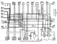
So...I'm not really sure where to look to solve this. I checked the wiring diagram (attached below) and I'm stumped on how the signal light dash indicators are wired...because it has what appears to be 2 power wires running to it. The light blue wire from the right side signal light power and orange wire from the left side signal lights power. How does that work???

Any advice would be greatly appreciated!

1695919606450.png
1695919614287.png
 

Attachments

  • 1695919565831.png
    1695919565831.png
    1.6 KB · Views: 7
Thinking about this now it seems odd because wouldn't there have needed to be a diode in place for this warning indicator lamp to work originally? Because both the wires in the diagram going to the indicator are effectively power.


But in the same...how is this working without a ground?


So confused lol. Help! 🙂1695939007515.gif Should be so simple but it's not. The warning indicator lamp on the dash is effectively a 5th signal light (the bike has 4, 2 left 2 right) but getting it to work with either left OR right signal is the confusing part as it's got 2 power wires running to it.
 
the frame is grounded and the lamp holder is making the circuit through it , if anything like the c90 i rode as a kid, each wire to the panel indicator is a feed piggybacked off the flashing circuit Left Or Right, so the panel indicator flashes in unison with the indicators

*EDIT If the panel indicator appears to be isolated from the frame the speedo lamp and the hi beam indicator are both directly earthed via the green wire and could be sharing that connection with the other panel indicators. test continuity between the lamp holders to validate a ground connection.
 
Last edited:
the frame is grounded and the lamp holder is making the circuit through it , if anything like the c90 i rode as a kid, each wire to the panel indicator is a feed piggybacked off the flashing circuit Left Or Right, so the panel indicator flashes in unison with the indicators
Interesting! Very interesting.

Makes sense what you say but I'm curious how the lamp holder would be grounded because it's a rubberized socket holding a wedge bulb. And I'm pretty sure it's inserted into a plastic (non grounded) bulb holder.


I'll take a better look tonight and at least I have more to go off! Thank you!
 
So I'm no further ahead. I monkeyed around it for a while tonight...no luck.

My other dash lights work just fine, like the high beam light and instrument cluster backlight. But they are super straight forward. They (the high beam and instrument backlight) both have a power and ground wire. So it's easy and logical how they light up.

All the dash indicators utilize the same rubber plug type socket with a standard wedge bulb that inserts in. Just 2 wires.

Every google search I do on how to wire a dash indicator for signal lights comes back with needing a diode if 2 power wires are running to the light. But there is nothing of the sort on the wiring diagram.

Any more suggestions would be appreciated. I'm totally stumped!
 
Pictures would help a lot I have a sketchy recollection of a bike i stripped down as a teen for track racing and more recently commuted on a honda tc360 that needed daily persuasion to run about 30 yrs ago, and while i have a 76 750 F1 in the garage ive not touched that yet, but i have a few old haynes and climer manuals and hondas all seemed to work the same and do things the same well back in the 70's anyway..

I would suggest trying to ground the bulb holder to the frame but that may not be reasonable suggestion.

Is the circuit getting grounded in the indicator switch?

ive blown the pic up but its not very clear but there are small boxes over the black wires feeding into the indicator junctions between the stop switch and front brake light switch positions ? diodes? or fuses?
 
I am having trouble following where each wire goes in the diagram; I'm too tired to follow them corectly. So:

Are the doublesquare indications on the diagram a parallel connection, or a series one?

If the indicator is wired so that the blinker switch places it in series with the blinked bulbs, then it would flash whenever they do.

If the blinker switch is wired to ground the opposing side of the indicator while powering the other from teh blinker, then it would flash when they do. The ground wouldn't be used by the actual signals, so if that was a bad connection in the switch or it's wiring, it would let the singals work but not the indicator.
 
Are the doublesquare indications on the diagram a parallel connection, or a series one?
bullet connectors and wire junctions 2 into 1 wire the circle end is the male its the end of the loom and start of the front/back leads
black dots are hard connections and crossing wires are not connected.

DOH!!!!

follow ground from the RHfront indicator bulb (top left) it goes through the bulb and back through the black lead into the junction (bullet connector?) with the grey wire leading to the panel indicator,

Same for the LH circuit, when the switch pulls high or +ve for left or right it should be automatically grounded via the actual indicator bulb its in circuit with

yeah, live or +ve comes into the switch via the indicator relay (flasher) and is directed as above..

trace it with a meter set to continuity deoxit is good for old dirty connectors....

edit..
you have been looking for discrete circuits for each lamp, as was I to start with.. the circuit and switch are orientated to chain the indicator with the panel indicator in series to activate

its been a long night eh?
 
Last edited:
and for the rear indicators they are both live 100% all the time its the connection to ground via the switched live at the front end that makes thier respective circuits too. via grey for the rh rear and yellow for the lh rear..
 
Hi guys. I've attached a more clear (but black and white) wiring diagram. Hopefully this helps shed some light (pun intended) on the situation.

Thanks!
 

Attachments

  • XL80 XL100 wiring 84 85.jpg
    XL80 XL100 wiring 84 85.jpg
    144.5 KB · Views: 2
and for the rear indicators they are both live 100% all the time its the connection to ground via the switched live at the front end that makes thier respective circuits too. via grey for the rh rear and yellow for the lh rear..
Hi Fill. It sounds like you've got it figured out. I just can't figure out what you're figuring lol. Can you help me explain?

I took a black and white version of the wiring diagram and drew in what I did. I only drew in the signal light wires as the wires running to the switch is stock and I didn't touch any of that. As mentioned, the signal lights work perfectly fine...it's just that darn dash indicator for the signal lights that has me confused to all heck.

I'm using a rubber signal light stalk to hold the signal lights (original was steel) so I ended up running a ground wire directly from the signal lights all the way to the grounding wire bullet connectors in the wire harness.

To me I'm still dumbfounded 'how' this is supposed to work. I still see 2 power wires (an orange and light blue) running into the dash indicator bulb for the signal lights. I just don't get it! Sorry :-( Hope my drawing helps...xl80 wiring diagram-.png
 
Start a trace at the left hand front indicator lamp, the diagram indicates (to me at least) that each front indicator is grounded to the frame.

stay with me a second.. forgive me if this is unnecessary..
now think about dc electric circuits, picture a battery and a lamp wired without a switch. now pick any point on any wire to consider, one side of the point is + the other is - , now move along the wire an inch or two to select a new point towards the + side. , The new point still has a + side and a -ve side and the bit of wire that was + for the last point is now coverd by the -ve side of the new point.. This is the crucial concept..

So back to the circuit trace, forget how just consider the indicator your starting with is ON its grounded to the frame so trace back the '+ve' feed to follow how the ground progresses back around the circuit..

I know im not explaining well.... but the black wire feeding +ve to the bulb is conversely feeding ground back round the circuit too, hence the black colour. ( orange in your above trace for the LH Front indicator)
trace that orange wire (ground) back to the junction where it branches off to the panel indicator and to the rear indicator to complete that aspect of the circuit. as it is ground and the other wire/side is live.


sorry for not being clearer,
 
Last edited:
Motorcycles employ the frame/motor as a common ground to save on expensive hi power copper wires for the ignition circuit. (not an engineer just assuming)
Ebikes use discrete circuits to feed power to components as needed with no common ground, I think we both started looking at this from an ebike frame of mind.. well i did for sure..
 
The indicator warning lamp does not have power on both sides when the lamp is not lit (indicator switch not set to left or right) . When the indicator switch is moved to indicate a turn, power on one side of the warning indicator is supplied from the bulb circuit that is activated ( left or right). The ground is provided through the filaments of the opposite bulbs.
 
The indicator warning lamp does not have power on both sides when the lamp is not lit (indicator switch not set to left or right) . When the indicator switch is moved to indicate a turn, power on one side of the warning indicator is supplied from the bulb circuit that is activated ( left or right). The ground is provided through the filaments of the opposite bulbs.
WOT HE SAID!,
 
Thanks guys. I get what you're saying...I think.

But doesn't that mean what I have wired should be working then?

If I do have something wrong (drawin in color on the b&w wiring diagram above) could someone draw in what I SHOULD be doing?

The only thing I did different from the wiring diagram was skip the grounding of the front signal light to the frame, and instead ran the ground wire directly back to a common ground in the wiring harness.

Notice the rear indicator lights don't frame ground but rather run into the wiring harness ground. Id imagine doing the same for the fronts would be ok.

Thanks for being patient with me guys :)
 
OK! I had a breakthrough! I got it to work without changing any wiring

One point I forgot to mention (I thought it was irrelevant) is that I was running LED signal lights (along with a LED flasher relay). With this, my dash indicator bulbs are also LED's.

So first off, just for fun (I was straight out of idea's) I pulled the LED DASH bulb out of the holder and replaced it with the original 1.7W incandescent one. And when I activated the signal lights ALL 4 signal lights came on... But I could see a SUPER faint glow from the incandescent bulb that flashed with the signal lights. So I was thinking...Ok...i'm on to something.

So then I left the incandescent 1.7W indicator bulb in the dash socket and replaced just the front RIGHT signal light from LED to the original 5w incandescent one. All the other 3 signal lights remained LED. And now when I signal LEFT, the dash bulb lights up as it should and the signals lights work. Perfect. But when I signal RIGHT, then all 4 signal lights come on (and the dash indicator bulb does not).

So I replaced the LEFT LED with a incandescent bulb as well, and now everything works as it should. Kind of. It sucks I have to run the front signals as incandescent (as this bike has a wussy charging system and puny battery) but then I figured if the dash indicator is working as it should now, then I could at least replace IT with LED.

Yes...and no. With the incansecent front signal lights and rear LED signal lights and the dash bulb as LED...the LED dash bulb will ONLY illuminate with the signal lights in one direction. Example, if I signal left...the LED dash bulb comes on. If I signal right...the LED dash bulb WON'T come on. Change the dash bulb back to incandescent, and the dash bulb works fine.

But if I take the LED dash bulb out and flip it 180 degrees and insert it back into the socket, then it will only illuminate when I signal right...but not left.

I have no clue how/why...

Funny thing is if I left all the signal lights as LED's and instead trying to have the single dash indicator bulb instead wired in 2 mini led's to shove into the socket where one LED would act as the left bank of lights and one of the other LED's would act as the right back...then I'd be fine.

Curious if this all makes sense as to why this happens with the LED's specifically.

Thanks!
 
Last edited:
LED bulbs are usually polarized--they only pass current one way.

(some are not, tyipcally those designed for sockets that a bulb can be inserted either way must be unpolarized, but any socket that only fits a bulb one way doesn't require this adaptation).

The indicator bulb design here requires current to flow either way at need, and that can't happen if it's an LED.

Also, LED bulbs usually use far less current, which means an incandescent in series with an LED probably won't have enough current light properly, if at all.

That same issue can also cause problems with the blinkers--old thermal blinkers require a certain amount of current to flow for them to operate. LED-compatible blinkers are usually electronic, rather than the old thermal type, or the old resistor-capacitor-relay type.

They make and sell "ballast" units to use in parallel with LED bulbs to work around these problems for vehicles that would otherwise require modification to operate correctly with LEDs. They are just large resistors that waste power as heat, just there to provide the extra current flow the other parts need to work right, while also dropping enough voltage across the resistor to still operate the LED in parallel with it.
 
Last edited:
So I went ahead and did this to my indicator bulb(image below)...works perfectly. I now have a full LED setup plus I spread the bulbs apart as far as I could so that you can tell if the left or right indicator is on.

Funny how many hours I wasted trying to figure out that dang single bulb setup. But I want LED all around and now the indicator bulbs are just miniature signal lights crammed into the single indicator housing!

1696266763263.png
 
Back
Top