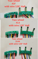
source for hall sensor mounted on PCB & wiring

EZgo

1 W
Joined
Sep 10, 2012
Messages
62
Location
Carlisle, PA
I rewired my 2014 9c motor cause the insulation had gone bad on 1 of the phase wires & 2 or 3 of the signal wires. This motor had always run great until it didn't. I bench tested it today using a spare controller & throttle & got nothin. Apparently the bad wiring caused 1 or more of the hall sensors to fail.

My 2 questions are: what is a good source to buy the 3 halls already mounted to the PCB? and 2, does it matter the order of the wiring?
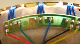
I have looked at about 6 of them & the halls & the PCB look identical to mine but the wiring is in a different order. A picture of my PCB w/halls is below.

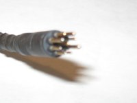
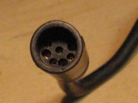
I also put a picture of the 9 pin wiring harness I need. I think I can get it from Grin but it would be great to know what it's called.

I also included a pic of my bike if anybody's interested. It's ready to roll but I really would like to get my old 10x6 wheel back on cause the 6x10 I bought by mistake is way to slow. I use this as my daily transport & often cruise at 25mph.

IMG_0503.JPG
IMG_0507.JPG
IMG_0580.JPG
 

Attachments

  • IMG_0460.JPG
    IMG_0460.JPG
    2.1 MB · Views: 610
If by wiring order you mean the three hall signals, you can fix those easily by desoldering and resoldering them in the order you prefer with the new cable you're going to be installing on it anyway.

*Because any cable you get with that connector on it won't pass thru the axle hole so you have to disconnect the cable from the board before installing the replacement cable thru the axle.

*or because any board you get with no cable on it you'd need to solder your cable to...

Not all PCBs will be identical traces, so you may even find the pad order at the board edge (if any) doesn't match the order of the halls on the board.

So you wire your cable to the board in the order that gets you the same wire color you previously used on the same hall in the sequence. If the most-counter-clockwise hall used the green wire before, you solder that to whatever pad puts that wire on the most-counterclockwise hall of the new board. Same for center and most-clockwise halls.

The 5v and ground wires are probably marked; if not they can be traced to the pins on the halls easily enough to find out which is which, and refer to a pinout of the hall sensor on the spec sheet to verify.


The 9-pin motor cable you're after is usually called Julet z-910 ; see the link E-HP provided.
 
Thanks so much.

As I started looking closely at some of these boards I realized that the plus & neg. where marked and as some of these had wires attached (even though they have to de-soldered) the signal wires where actually in the correct order.

And speaking of fitting through the axel hole. I did not have a small male 9pin like was on it so I used the bigger 3 pin/6contact plug. As I mounted it in my old bike fork for testing I groaned & cursed as I realized that the axel nut & washers where not even close to sliding over that big end. So I'm kinda glad it didn't work cause everything has to come out.

Grin does have a 9pin motor extension cable that looks Identical. I'm going to email them & ask them about a 9 pin harness. If they don't have one I'll just order that extension cable
 
BTW, if you haven't actually *tested* the hall sensors, I recommend doing that first.

Since you have the stator out of the motor, you just have to connect them to a controller like normal, and power on the controller. Setup voltmeter on 20VDC, black on battery negative, red to first hall signal.

pass a small magnet (namebadge, etc) over the hall under test, slowly, and see if the voltage changes. If it was near zero volts to start with, it should go to near 5v. Or vice-versa. Turn the magnet 180 degrees, and pass it over the hall again. Reading should swap the other way.

Do the same for each of the other two halls.

Any that don't change are probably failed.

If the magnet is not strong enough (like a fridge magnet, etc) then it won't switch the hall output.
 
amberwolf said:
BTW, if you haven't actually *tested* the hall sensors, I recommend doing that first.

Since you have the stator out of the motor, you just have to connect them to a controller like normal, and power on the controller. Setup voltmeter on 20VDC, black on battery negative, red to first hall signal.

pass a small magnet (namebadge, etc) over the hall under test, slowly, and see if the voltage changes. If it was near zero volts to start with, it should go to near 5v. Or vice-versa. Turn the magnet 180 degrees, and pass it over the hall again. Reading should swap the other way.

Do the same for each of the other two halls.

Any that don't change are probably failed.

If the magnet is not strong enough (like a fridge magnet, etc) then it won't switch the hall output.

I was going to ask that question but forgot. You say turn the rotor 180.
Does that mean I should have the stator sitting in the field or am I just moving the magnet around the stator 180?

Another question and I was going to experiment with this one providing their bad. Is it possible to remove the halls with out destroying them. I watched Grins video on changing halls & he mentions gluing them in. I have an unused 700c front 9c from 2014. (same motor different shaft) If there is any chance I can remove the halls from the stator I'm going to try. Thank you
 
EZgo said:
amberwolf said:
BTW, if you haven't actually *tested* the hall sensors, I recommend doing that first.

Since you have the stator out of the motor, you just have to connect them to a controller like normal, and power on the controller. Setup voltmeter on 20VDC, black on battery negative, red to first hall signal.

pass a small magnet (namebadge, etc) over the hall under test, slowly, and see if the voltage changes. If it was near zero volts to start with, it should go to near 5v. Or vice-versa. Turn the magnet 180 degrees, and pass it over the hall again. Reading should swap the other way.

Do the same for each of the other two halls.

Any that don't change are probably failed.

If the magnet is not strong enough (like a fridge magnet, etc) then it won't switch the hall output.

I was going to ask that question but forgot. You say turn the rotor 180.
Does that mean I should have the stator sitting in the field or am I just moving the magnet around the stator 180?

Another question and I was going to experiment with this one providing their bad. Is it possible to remove the halls with out destroying them. I watched Grins video on changing halls & he mentions gluing them in. I have an unused 700c front 9c from 2014. (same motor different shaft) If there is any chance I can remove the halls from the stator I'm going to try. Thank you

All of my halls where bad. To make sure I was testing them correctly (I thought all 3 being bad was odd) I took apart my unused 2014 wheel & they tested exactly as you said they should.

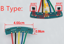
Below is a screen shot of the halls & board I think I need. My question again is the order of things. This new board is clearly marked. My old board isn't. Is ABC always left to right? The wires have to be de-soldered anyway but I'm unsure if I should put my 3 hall wires on the new board in the same order as they where or not.

I've tried to trace the circuit on the board but what I think I see doesn't make sense. Unless the hall wires themselves are not supposed to make contact to the right side wire of each hall.
HallSensor.png
 
EZgo said:
Another question and I was going to experiment with this one providing their bad. Is it possible to remove the halls with out destroying them. I watched Grins video on changing halls & he mentions gluing them in. I have an unused 700c front 9c from 2014. (same motor different shaft) If there is any chance I can remove the halls from the stator I'm going to try. Thank you
Generally they slide right out; when moutned to a board they are rarely even glued in, because the board itself is usually tied down to the windings.

So you can just buy a handful of new honeywell SS411A type digital latching hall sensors (if you just buy three, something is guaranteed to go wrong and break one :lol: ), and desolder the first old one from the board, then install the first new one just like the old one was (same orientation), then replace the next, and then the last. If you take them all out at once you don't have a handy reference right there for how to isntall them. ;)
 
EZgo said:
All of my halls where bad. To make sure I was testing them correctly (I thought all 3 being bad was odd) I took apart my unused 2014 wheel & they tested exactly as you said they should.

It's easy to kill all the halls if a phase wire shorts to the 5v supply (this also usually kills the controller and the throttle and PAS sensors because they're all on that 5v supply, unless the controller uses a diode on the motor hall 5v output; some do, some don't.

Below is a screen shot of the halls & board I think I need. My question again is the order of things. This new board is clearly marked. My old board isn't. Is ABC always left to right? The wires have to be de-soldered anyway but I'm unsure if I should put my 3 hall wires on the new board in the same order as they where or not.

I've tried to trace the circuit on the board but what I think I see doesn't make sense. Unless the hall wires themselves are not supposed to make contact to the right side wire of each hall.
I'm nto sure what you mean. In this screenshot of a 60-degree-type hall board (where the center hall is flipped, in this case by using a completely different hall part number!) I see traces from each incoming wire to each hall pin, as I'd expect. 5V is on the sensor side of the board with the A hall signal, and the ground and B and C signals are on the solder side. The B signal goes to the *left* pin because the sensor is "flipped" (using a different hall part with different wiring).

However, your board should look different than that because it ought to be a 120-degree-style board, where the center hall is NOT flipped, and has the same wiring order as the other two. I can't clearly see your hall orientation where they go into the stator here
https://endless-sphere.com/forums/download/file.php?id=313601
but the three pads are the same order on all three PCB areas, so it's pretty likely yours are all oriented the same and not flipped (meaning, you don't want to use the board you screenshotted, unless your controller can automatically determine 60/120 hall "spacing"/timing, or there is a jumper for it you can solder on the controller PCB).
 
amberwolf said:
EZgo said:
All of my halls where bad. To make sure I was testing them correctly (I thought all 3 being bad was odd) I took apart my unused 2014 wheel & they tested exactly as you said they should.

It's easy to kill all the halls if a phase wire shorts to the 5v supply (this also usually kills the controller and the throttle and PAS sensors because they're all on that 5v supply, unless the controller uses a diode on the motor hall 5v output; some do, some don't.

Below is a screen shot of the halls & board I think I need. My question again is the order of things. This new board is clearly marked. My old board isn't. Is ABC always left to right? The wires have to be de-soldered anyway but I'm unsure if I should put my 3 hall wires on the new board in the same order as they where or not.

I've tried to trace the circuit on the board but what I think I see doesn't make sense. Unless the hall wires themselves are not supposed to make contact to the right side wire of each hall.
I'm nto sure what you mean. In this screenshot of a 60-degree-type hall board (where the center hall is flipped, in this case by using a completely different hall part number!) I see traces from each incoming wire to each hall pin, as I'd expect. 5V is on the sensor side of the board with the A hall signal, and the ground and B and C signals are on the solder side. The B signal goes to the *left* pin because the sensor is "flipped" (using a different hall part with different wiring).

However, your board should look different than that because it ought to be a 120-degree-style board, where the center hall is NOT flipped, and has the same wiring order as the other two. I can't clearly see your hall orientation where they go into the stator here
https://endless-sphere.com/forums/download/file.php?id=313601
but the three pads are the same order on all three PCB areas, so it's pretty likely yours are all oriented the same and not flipped (meaning, you don't want to use the board you screenshotted, unless your controller can automatically determine 60/120 hall "spacing"/timing, or there is a jumper for it you can solder on the controller PCB).

When you say flipped you mean the signal side is different than the others? I just ordered some SS41 Hall Sensors from Grin & the page shows the + - & signal. That was a big help. As for 60 versus 120 degrees my board does say 120 & I see the 60 on the screen shot but the measurements including the spacing are Identical. Do the degrees refer to that flipped hall in the middle? Please excuse all my questions but I've learned more about the inner workings of these motors in the last week than in all the years I was selling & installing ebike kits.

I had one hall sensor I had to chisel out, I broke the wires on another & the only one that came out easy was the middle. So I decided to leave the new motor alone & I'll just use it has a teaching tool.
 
EZgo said:
When you say flipped you mean the signal side is different than the others?
What flipped really means is that the reading you get from the center sensor in the 60 degree version will be the reverse of what it is with the 120 degree version. So the hall signal set that would come from a 60 motor might be 000, where a 120 can never get that, it would end up 010 instead, as the signals toggle back and forth as magnets pass across them during rotation. If the controller doesn't know that's what it's looking at, it either just shutsdown for a "hall error" or it miscommutates the motor and it doesn't spin the way it should (if at all).

The 60 degree setup may or may not have the pin order different on each sensor, and the housings may or may not be different or even have different part numbers, etc. Some of them literally just flip the center sensor over so it faces down instead of up, so the transitions occur in the other direction and it toggles the opposite way it would have otherwise.

I just ordered some SS41 Hall Sensors from Grin & the page shows the + - & signal. That was a big help.
Yeah, basically any of hte ss41 / ss411 types can work, the main differences are in temperature and voltage tolerances, and sometimes the magnetic strenght needed to trigger signal change--but that type generally will work with any common ebike controller.

As for 60 versus 120 degrees my board does say 120 & I see the 60 on the screen shot but the measurements including the spacing are Identical. Do the degrees refer to that flipped hall in the middle?

Everything in a setup like that is physically identical, they just flip the center sensor so it's response to the magnets is reversed.

The term 60 degree / 120 degree refers to the "electrical" degrees of rotation of the fields. You can actually put sensors (not flpped) at 60 degree phsyical spacing around the circle of the stator, and it would work exactly the same. Same for 120--put them in an equilateral triangle around the stator, and they'll work just like they do in the short line. They don't usually do this because it's eaiser and faster and cheaper to build if they can stick them on a board and shove it in, tie it down, and be done with it, rather than putting individual sensors into individual slots and tie down all those separate wires, etc.

But i did the 120-degree physical spacing on this motor:
https://endless-sphere.com/forums/viewtopic.php?f=30&t=32838&start=25#p504935
DSC05513[1].JPG
DSC05516[1].JPG
and it did work.

I had one hall sensor I had to chisel out, I broke the wires on another & the only one that came out easy was the middle. So I decided to leave the new motor alone & I'll just use it has a teaching tool.

Sometimes they dont' come out easy; either becuase of glue or because the slots machined into the stator teeth aren't precisely made and grab the plastic of the sensor too hard. :(
 
amberwolf said:
EZgo said:
When you say flipped you mean the signal side is different than the others?
What flipped really means is that the reading you get from the center sensor in the 60 degree version will be the reverse of what it is with the 120 degree version. So the hall signal set that would come from a 60 motor might be 000, where a 120 can never get that, it would end up 010 instead, as the signals toggle back and forth as magnets pass across them during rotation. If the controller doesn't know that's what it's looking at, it either just shutsdown for a "hall error" or it miscommutates the motor and it doesn't spin the way it should (if at all).

The 60 degree setup may or may not have the pin order different on each sensor, and the housings may or may not be different or even have different part numbers, etc. Some of them literally just flip the center sensor over so it faces down instead of up, so the transitions occur in the other direction and it toggles the opposite way it would have otherwise.

I just ordered some SS41 Hall Sensors from Grin & the page shows the + - & signal. That was a big help.
Yeah, basically any of hte ss41 / ss411 types can work, the main differences are in temperature and voltage tolerances, and sometimes the magnetic strenght needed to trigger signal change--but that type generally will work with any common ebike controller.

As for 60 versus 120 degrees my board does say 120 & I see the 60 on the screen shot but the measurements including the spacing are Identical. Do the degrees refer to that flipped hall in the middle?

Everything in a setup like that is physically identical, they just flip the center sensor so it's response to the magnets is reversed.

The term 60 degree / 120 degree refers to the "electrical" degrees of rotation of the fields. You can actually put sensors (not flpped) at 60 degree phsyical spacing around the circle of the stator, and it would work exactly the same. Same for 120--put them in an equilateral triangle around the stator, and they'll work just like they do in the short line. They don't usually do this because it's eaiser and faster and cheaper to build if they can stick them on a board and shove it in, tie it down, and be done with it, rather than putting individual sensors into individual slots and tie down all those separate wires, etc.

But i did the 120-degree physical spacing on this motor:
https://endless-sphere.com/forums/viewtopic.php?f=30&t=32838&start=25#p504935
DSC05513[1].JPG
DSC05516[1].JPG
and it did work.

I had one hall sensor I had to chisel out, I broke the wires on another & the only one that came out easy was the middle. So I decided to leave the new motor alone & I'll just use it has a teaching tool.

Sometimes they dont' come out easy; either becuase of glue or because the slots machined into the stator teeth aren't precisely made and grab the plastic of the sensor too hard. :(

I'm now pretty clear as to how this all works but I'd still like to get a new board or board with halls but I can't seem to find one that is built the same as mine & I've looked at a lot. (I damaged mine & can't re-use it) Below is a good pic of the board on the new/old motor I have.
new.old.wheel.sm.png
It's very easy to trace so I can easily see which boards would work. I have found the ones below (plus the link) that look correct in every way but the the 5V only feeds the right side hall. I think part of the # refers to the hall itself but I'm not sure. I can run a separate 5v & neg. to each hall but my soldering skills are marginal & I didn't want to splice in extra wires.
3Halls.png
https://www.aliexpress.com/item/4001212690596.html?_randl_currency=USD&_randl_shipto=US&src=google&aff_fcid=9a2208b93bf94d799fcad4a6d7d3b1ab-1648135717358-09916-UneMJZVf&aff_fsk=UneMJZVf&aff_platform=aaf&sk=UneMJZVf&aff_trace_key=9a2208b93bf94d799fcad4a6d7d3b1ab-1648135717358-09916-UneMJZVf&terminal_id=daf0c478f83e4b80acf6d1975f01f051&afSmartRedirect=y
 
EZgo said:
I have found the ones below (plus the link) that look correct in every way but the the 5V only feeds the right side hall.
Oh, it feeds them all (they wont' work without it); it is just going from that one to the others on the "back" side of the board. See the trace along the top edge, under the sensor legs? Most PCBs don't route everything straight to everything else. THey could easily have made it a single-sided PCB with a couple tiny changes in pad placement for the wires.


think part of the # refers to the hall itself but I'm not sure.
Probably. There is an SS41F model, and another type ss413 (whcih also has a A and F versions), and an SS3144 as well. Some are bipolar (transitions on boht polarities of field), some are unipolar (only transitions on one polarity of field)

I can run a separate 5v & neg. to each hall but my soldering skills are marginal & I didn't want to splice in extra wires.
There's no need, it already has the traces. There would be no purpose to making a board that didn't power and ground all of the halls. ;)
 
Thank you. I looked at those pics off & on for 30 min & could not see that. It's clear now.
What I meant about splicing wires was in case I had to go without the pcb. Clearance inside this 9c looks pretty tight.

It appears then that the board shown in the 413 & 3144 pics would work even if the halls themselves need replaced. I got 9 halls from Grin so I have something to practice with.
 
As long as the hall board is made for 120, and has the same physical spacing of the halls as your slots, it would work with your motor/controller. Even if hte halls are a different kind, the motor will probably still operate the same way it did before (if not, it's not usually that big a deal to replace the halls on a PCB, nothing like trying to hand-wire them).

If you have to go without a PCB:

Cut three pieces of black wire to about 3" long.

Cut three pieces of red wire to about 3" long.

Cut about 3" off of the motor cable's red and black wires, to compensate for the above. (you can use those pieces as one each of the above 3 red/black wires).

Cut two pieces of 1/4" or so diameter heatshrink (big enough to just slip over a set of three wires held parallel), about an inch long.

Slip the heatshrink onto each of the motor red and black wires (not the six separate pieces).

Strip one end of each of those six wires and the motor cable's red and black wires about 1/4".

If you can do it, slightly spread the strands of wire on the motor cable's red and black wires, and those of one end of each of the six 3" pieces, so they are like an old paintbrush's bristles, just slightly spread away from each other.

Place all three 3" red wires in parallel, spread ends together, and "insert" the motor cable red wire into the "bundle" of strands, then "twist" the strands together so they trap each other. This may require practice, so use some old wire you don't need to practice this part before doing it with your real wires. The point is to get as much of each wire in contact with each other, so they "hold" each other together and depend least on the solder to hold together.

Solder this joint, and let it cool.

Repeat for the black wires.

Slide the heatshrink up from the motor wires over each joint, and shrink it. The idea is to completley cover all conducting materials.

Now you have power and ground wires for each hall. :)


Cut 9 pieces of heatshrink or teflon tubing (of a diameter that just barely fits over the leads, so it stays in place without being shrunk) of a length that is *just enough* to cover all but the last 1/4" (at most) of the leads. Use HS that is thin-walled, or else it may be too thick once shrunk to fit between cover and windigns.

Slip that over every lead of every hall. This will protect the leads from shorting to the windings even if winding insulation gets damaged somehow.

Slip each of the halls in the slots of the motor, narrow/beveled-side up, then tape them down with duct tape or something equally sticky, across the lead end of the hall plus a tiny bit of the covered leads.

Cut 9 pieces of heatshrink of a diameter about twice as large as the insulation on the wires you use, and about 1" long. Use HS that is thin-walled, or else it may be too thick once shrunk to fit between cover and windigns. I have an old Amped hub (just like a 9c) that had too-thick HS and it rubbed thru it and shorted a hall lead to the cover over time. :(

Slip that over every wire you are going to solder to the halls.

Strip the insulation on the end of each of those wires by 1/4" or less.

Use "helping hands" or some method of securing the wire to be soldered to the hall lead in place, so that you are not holding either hall lead or wire, and the bare wire overlaps the bare lead area completely. If the bare wire area is longer than the bare lead area, trim the bare wire till it is the same, so they perfectly overlap, if possible.

The helping hands/etc method will keep you from accidentally pushing on the hall lead back and forth in soldering, which will break them off, or fracture them so that when you flatten the leads against the windings they then break off (or later, after you've closed it all up and are riding, from vibration :( ).

Note that you can't directly clip the wire to the lead because the clip will suck the soldering heat away and keep it from making a good joint.

Solder the wire and let it cool.

Repeat for all 9 wires.

Slide the heatshrink up from the wire over the solder joints, and shrink them (this is best done all at once so you don't accidentally shrink the tubing on others not slid up onto the joints while shrinking the ones already on joints). The idea is to completley cover all conducting materials.


Carefully bend the covered leads straight down over the stator windings; you may form them into a curve by pressing on them, then use string (something that won't melt at potentially boiling water temperatures) to tie them all down to the windings (or to the existing string that's used on the windings, if you can't pass the string under the windings). Make sure your knot(s) is/are to the side of the windings so it doesn't make things any taller, to prevent rubbing on the sidecover.
 
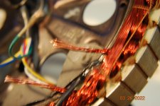
amberwolf said:
As long as the hall board is made for 120, and has the same physical spacing of the halls as your slots, it would work with your motor/controller. Even if hte halls are a different kind, the motor will probably still operate the same way it did before (if not, it's not usually that big a deal to replace the halls on a PCB, nothing like trying to hand-wire them).

If you have to go without a PCB:

Cut three pieces of black wire to about 3" long.

Cut three pieces of red wire to about 3" long.

Cut about 3" off of the motor cable's red and black wires, to compensate for the above. (you can use those pieces as one each of the above 3 red/black wires).

Cut two pieces of 1/4" or so diameter heatshrink (big enough to just slip over a set of three wires held parallel), about an inch long.

Slip the heatshrink onto each of the motor red and black wires (not the six separate pieces).

Strip one end of each of those six wires and the motor cable's red and black wires about 1/4".

If you can do it, slightly spread the strands of wire on the motor cable's red and black wires, and those of one end of each of the six 3" pieces, so they are like an old paintbrush's bristles, just slightly spread away from each other.

Place all three 3" red wires in parallel, spread ends together, and "insert" the motor cable red wire into the "bundle" of strands, then "twist" the strands together so they trap each other. This may require practice, so use some old wire you don't need to practice this part before doing it with your real wires. The point is to get as much of each wire in contact with each other, so they "hold" each other together and depend least on the solder to hold together.

Solder this joint, and let it cool.

Repeat for the black wires.

Slide the heatshrink up from the motor wires over each joint, and shrink it. The idea is to completley cover all conducting materials.

Now you have power and ground wires for each hall. :)


Cut 9 pieces of heatshrink or teflon tubing (of a diameter that just barely fits over the leads, so it stays in place without being shrunk) of a length that is *just enough* to cover all but the last 1/4" (at most) of the leads. Use HS that is thin-walled, or else it may be too thick once shrunk to fit between cover and windigns.

Slip that over every lead of every hall. This will protect the leads from shorting to the windings even if winding insulation gets damaged somehow.

Slip each of the halls in the slots of the motor, narrow/beveled-side up, then tape them down with duct tape or something equally sticky, across the lead end of the hall plus a tiny bit of the covered leads.

Cut 9 pieces of heatshrink of a diameter about twice as large as the insulation on the wires you use, and about 1" long. Use HS that is thin-walled, or else it may be too thick once shrunk to fit between cover and windigns. I have an old Amped hub (just like a 9c) that had too-thick HS and it rubbed thru it and shorted a hall lead to the cover over time. :(

Slip that over every wire you are going to solder to the halls.

Strip the insulation on the end of each of those wires by 1/4" or less.

Use "helping hands" or some method of securing the wire to be soldered to the hall lead in place, so that you are not holding either hall lead or wire, and the bare wire overlaps the bare lead area completely. If the bare wire area is longer than the bare lead area, trim the bare wire till it is the same, so they perfectly overlap, if possible.

The helping hands/etc method will keep you from accidentally pushing on the hall lead back and forth in soldering, which will break them off, or fracture them so that when you flatten the leads against the windings they then break off (or later, after you've closed it all up and are riding, from vibration :( ).

Note that you can't directly clip the wire to the lead because the clip will suck the soldering heat away and keep it from making a good joint.

Solder the wire and let it cool.

Repeat for all 9 wires.

Slide the heatshrink up from the wire over the solder joints, and shrink them (this is best done all at once so you don't accidentally shrink the tubing on others not slid up onto the joints while shrinking the ones already on joints). The idea is to completely cover all conducting materials.


Carefully bend the covered leads straight down over the stator windings; you may form them into a curve by pressing on them, then use string (something that won't melt at potentially boiling water temperatures) to tie them all down to the windings (or to the existing string that's used on the windings, if you can't pass the string under the windings). Make sure your knot(s) is/are to the side of the windings so it doesn't make things any taller, to prevent rubbing on the sidecover.

This is great. Thank you so much. I've watched 2 videos on this but although I got the general idea you really couldn't see the details. Also the end result on both videos looked a bit sloppy for my taste.

I have to have to redo all of my wiring on this motor cause I replaced my small Z910 9 pin with a big Julet Z916 plug & forgot to slide the wire through axel nut & washer. (kinda glad it didn't work) That said I could not get anything nearly as good as the original solder joint on the heavy phase wires. I'm assuming it was because of the different gauges, stiff coil wire mated to finely braided wire and or I did not get the coil wire clean enough or the old solder was different than the solder I was using. (I was using hi quality electronic solder)

Any tips for this part of the solder job?

Also I ordered the board & halls in lots of 5@ 41F, 413, & 3144 from Aliexpress. After I figure which one is the best fit (if any) I'll put the remainder on the online market & sell them for just the cost of mailing. I would for sure be lost without your help & this forum.
 
EZgo said:
This is great. Thank you so much. I've watched 2 videos on this but although I got the general idea you really couldn't see the details. Also the end result on both videos looked a bit sloppy for my taste.
Might be part of why I don't make videos / etc; my work often looks sloppy, because only I have to look at it :lol: but it does the job. ;)


I have to have to redo all of my wiring on this motor cause I replaced my small Z910 9 pin with a big Julet Z916 plug & forgot to slide the wire through axel nut & washer. (kinda glad it didn't work) That said I could not get anything nearly as good as the original solder joint on the heavy phase wires. I'm assuming it was because of the different gauges, stiff coil wire mated to finely braided wire and or I did not get the coil wire clean enough or the old solder was different than the solder I was using. (I was using hi quality electronic solder)

Any tips for this part of the solder job?

First, use a finger-sized tip for your iron, and use an iron that is at least 80-100w. Temperature controlled is best, but I just use an 80w Weller with fingersized chisel tip for anything big.

If the iron can't put enough heat in fast enough it won't make a good joint, and it also can damage the insulation nearby (and if attached to electronics close by could damage those if they overheat).

Spinningmagnets posted a guide with better pics than mine, but showing my method for joining large wires, etc.:
https://www.electricbike.com/connectors-halls-throttle-motor/
I have a few posts about it, but this one still has most of the pics:
https://endless-sphere.com/forums/viewtopic.php?f=2&t=86600&p=1463159&hilit=solder%2A+phase%2A+stromer#p1463762
 
amberwolf said:
EZgo said:
This is great. Thank you so much. I've watched 2 videos on this but although I got the general idea you really couldn't see the details. Also the end result on both videos looked a bit sloppy for my taste.
Might be part of why I don't make videos / etc; my work often looks sloppy, because only I have to look at it :lol: but it does the job. ;)


I have to have to redo all of my wiring on this motor cause I replaced my small Z910 9 pin with a big Julet Z916 plug & forgot to slide the wire through axel nut & washer. (kinda glad it didn't work) That said I could not get anything nearly as good as the original solder joint on the heavy phase wires. I'm assuming it was because of the different gauges, stiff coil wire mated to finely braided wire and or I did not get the coil wire clean enough or the old solder was different than the solder I was using. (I was using hi quality electronic solder)

Any tips for this part of the solder job?

First, use a finger-sized tip for your iron, and use an iron that is at least 80-100w. Temperature controlled is best, but I just use an 80w Weller with fingersized chisel tip for anything big.

If the iron can't put enough heat in fast enough it won't make a good joint, and it also can damage the insulation nearby (and if attached to electronics close by could damage those if they overheat).

Spinningmagnets posted a guide with better pics than mine, but showing my method for joining large wires, etc.:
https://www.electricbike.com/connectors-halls-throttle-motor/
I have a few posts about it, but this one still has most of the pics:
https://endless-sphere.com/forums/viewtopic.php?f=2&t=86600&p=1463159&hilit=solder%2A+phase%2A+stromer#p1463762
Thank you, Both where very helpful. I use a butane solder iron but I was using the wrong tip. 2nd mistake was when I de-soldered the old wire I left the remaining solder on the coil wire & attempted to wrap the new wire around the old wire w/solder & it looked pretty pad. I use a heavy shrink wrap with adhesive inside & I was hoping that would make up for my crapy soldering. Although I worried about the glue getting soft If & when those coil wires got hot.
 
Quick question. I bought a box of insulated solder seal butt connectors sometime ago & have never used. Would they work well for connecting the phase wires to the coil wires?
 
There is probably not enough solder in them to do it (or enough flux), and to heat them up enough to get the solder to melt into the wires will probably destroy the heatshrink.

That was the case with the cheap ones I tried off Amazon:
https://www.amazon.com/gp/product/B07R4Z13P3/ref=ppx_yo_dt_b_search_asin_title?ie=UTF8&psc=1
They sort of work ok on small thin wires; anything with enough copper to require a big iron to do soldering on just doesn't get the copper hot enough for the solder to do it's job.

You'd be better off with crimping lugs like these:
https://www.amazon.com/gp/product/B076H3VHGN/ref=ppx_yo_dt_b_search_asin_title?ie=UTF8&psc=1
which *did* work. I crimped them, but you could also solder them (or both). A good crimp shouldn't need solder, and will be a better connection, because it turns the entire connection into a single piece of metal...but it may take a hydraulic or ratcheting crimper to do it, and you have to use the right die size/shape for each different kind of contact / etc that you crimp onto a wire.
 
Thanks. That's kinda of what I thought. I already soldered them using your technique & it worked much better. I did scrape each strand of the coil wire shiny bright. It was a bit of a pain but I think it helped the solder stick. Why is the original wiring (on a 9c DD anyway) twist the wire (like house wiring that's been wire nutted) & then solder the wire? That's how I did it the first time.
CoilWire.JPG
 
EZgo said:
I did scrape each strand of the coil wire shiny bright. It was a bit of a pain but I think it helped the solder stick.
If you mean that you removed the enamel from the wire: if you don't do that then it's still insulated against current flow, so it wouldn't work (wouldn't solder either). ;)

There are tricks to remove that stuff if necessary; someone here (dogman?) used aspirin heated with the soldering iron to help remove it; I've never tried that.


Why is the original wiring (on a 9c DD anyway) twist the wire (like house wiring that's been wire nutted) & then solder the wire?
Because it's very quick to do, which means it's very cheap to do. Cheaper is always better, it means more profit. ;)

Non-cheap ways are only used where they won't work, or will result in too many unhappy customers (there is always an allowable amount).
 
amberwolf said:
EZgo said:
I have found the ones below (plus the link) that look correct in every way but the the 5V only feeds the right side hall.
Oh, it feeds them all (they wont' work without it); it is just going from that one to the others on the "back" side of the board. See the trace along the top edge, under the sensor legs? Most PCBs don't route everything straight to everything else. THey could easily have made it a single-sided PCB with a couple tiny changes in pad placement for the wires.


think part of the # refers to the hall itself but I'm not sure.
Probably. There is an SS41F model, and another type ss413 (whcih also has a A and F versions), and an SS3144 as well. Some are bipolar (transitions on boht polarities of field), some are unipolar (only transitions on one polarity of field)

I can run a separate 5v & neg. to each hall but my soldering skills are marginal & I didn't want to splice in extra wires.
There's no need, it already has the traces. There would be no purpose to making a board that didn't power and ground all of the halls. ;)
I finally got the pcb's from Aliexpress. (took a month) The boards are identical & the halls physically appear identical. They are all digital bipolar hall-effct senor IC's. The 3 type of halls are: 41F, 413, & 3144. I'm going to use the board with the 41F halls. Grins hall's are a S41. If the 41F works great, if not I'll resolder the pcb with the halls from Grin. I have plenty of boards to play with.
 
Back
Top