Speedometer glitch reading 99+ mph

speedbiker

1 mW
Joined
Sep 4, 2023
Messages
15
Location
Boston
Hello, I have a phaserunner v6 controller, cycleanalyst v3 display, and I have an external speedometer. It's a circular 3 pin connection that leads into the bafang motor casing, and then assumedly to the phaserunner through the motor plug. The hall sensor is lost, so the 3 pin connector is unplugged right now.

Here's whats happening: When the throttle is pressed, there's no response. Only when it's pressed more than halfway down, does the motor start turning the wheel slowly. Here's where the CA displays 99+ mph. And, when throttle is released, the motor keeps spinning the wheel faster and faster. I don't know if this is normal behavior from an unplugged speed sensor.

According to the phaserunner manual, it auto select the source of the wheel speed signal between "wheel speed sensor pin" (I assume this is the hall plug), or if no speed pulses are detected after the motor is spinning, then the "motor Hall signals" get fed to the CA speed signal input. So I would expect the bike to run fine with the external speed sensor unplugged.

Now, I don't know what to do to fix it - I could buy a new 3 pin hall sensor and try plugging that in, but right now I have a 2 pin reed sensor. I've tried hooking it up to the 3 pin hall plug, and same error occurs. I was told that to hook up the reed sensor, the ground goes to the hall plug ground, and the red goes to the "white speed wire coming out of the controller". However, there is no white wire coming from the phaserunner! Only one thick black cable (motor plug), and 2 other black cables (mains signals, PAS torque plug).

So I would really appreciate advice:
  • How do I hook up the 2 pin reed sensor to my current setup (what is that "white wire", or is there a different way to do it)
  • Would buying a new hall sensor solve the problem, or is there issues with other components? Hall Sensor: Amazon.com
  • @amberwolf suggested that I GROUND the signal line on the hall plug, to stop the glitch and allow me to ride. The problem is, i checked with a multimeter, and 2 of the pins are +5v, and one of them seems to be ground. So, I don't know which pin is the signal line. The fact that there are 2 5v pins makes me think a new 3 pin hall sensor would not work.
 
USER=13812]@amberwolf[/USER] suggested that I GROUND the signal line on the hall plug, to stop the glitch and allow me to ride. The problem is, i checked with a multimeter, and 2 of the pins are +5v, and one of them seems to be ground. So, I don't know which pin is the signal line. The fact that there are 2 5v pins makes me think a new 3 pin hall sensor would not work.
amberwolf cautioned you against grounding the wrong 5v line, but it appears you grounded both
“I measured the.3 lines with multimeter, 2 are 5v 1 is ground i guess I tried grounding one then the other, both times, it just disabled the throttle.”


Grounding the 5v supply line can fry the circuit, so $$ down the drain. Luckily the PR may have some fault protection to protect it from the user, but most controllers don’t. The reason the signal wire would be 5v is because internally there’s a pull up resistor keeping the signal in the high state until it’s grounded.

You don’t mention what motor you have or other details about your system, so hard to tell what’s up. The external speed sensor cable going to the motor is unusual, unless by motor you mean a mid drive.
 
Motor is a Bafang bbshd mid-drive motor
Phaserunner v6 controller
Cycle analyst v3 display
72v 19.2ah 60a BMS battery

Are there any other details needed? The speed cable goes into the mid drive motor casing.


The reason the signal wire would be 5v is because internally there’s a pull up resistor keeping the signal in the high state until it’s grounded.
So does this mean I just have to ground the signal wire to make it go back to 0v, and then with it grounded, the bug should resolve? If so, how do I know which 5v line is the signal line?
 
Yes, the throttle and speedometer functioned fine, then I believe I hit a bump, and it stopped working from that point on. I forgot exactly how it started, pretty sure it was a bump.
 
What about the 2 5v lines?
Do I just have to ground the signal wire to make it go back to 0v, and then with it grounded, the bug should resolve? If so, how do I know which 5v line is the signal line?

Also, how do I connect the 2 pin reed sensor up to the "white speed wire" ?
 
Ya, makes sense now. How comfortable are you with opening the motor? With the conversion, it’s unclear why the speed signal needs to be routed through the motor housing, so seeing how it’s wired internally might provide some clues. It also could be where the problem lies.
 
I would be able to do that in the future, but first I would like to try:
  1. Grounding the hall plug - How do I know which 5v line is the signal
  2. Connecting the 2 pin reed sensor up - Don't know how to connect it, would need advice (what is the white speed wire coming from the controller)
  3. Buying a new 3 pin hall sensor - would need to fix the 2 5v before hooking this up
 
I would be able to do that in the future, but first I would like to try:
No, you have bigger problems and messing around putting $500 of quality hardware at risk, which you already have done, is not a prudent course.

The behavior below is not normal in any condition, but could indicate a hardware fault. The motor spinning without throttle being applied points to a possible faulty ground conductor between the CA and the throttle, or PR, depending on how the person who converted the system wired it.
Here's whats happening: When the throttle is pressed, there's no response. Only when it's pressed more than halfway down, does the motor start turning the wheel slowly. Here's where the CA displays 99+ mph. And, when throttle is released, the motor keeps spinning the wheel faster and faster. I don't know if this is normal behavior from an unplugged speed sensor.
The advice amberwolf provided you was absent the knowledge that you just shared that your motor is the BBSHD. (and that you didn't perform the conversion). Nonetheless, he even states, that it doesn't make sense that the sensor would go to the motor, and then he provided the same advice, that IF it did go to the motor, then you'd need to trace the path from the sensor all the way to the CA (or PR). So, if you haven't done that after 8 months, then how far into the future are you talking??

At minimum, you need to provide more info on your system. What model PR, pictures of how it was wired, type of throttle, and where it's connected (CA or PR), any other accessories or buttons connected to either, etc. Both units are very flexible and they can be connected in a variety of ways.
 
Last edited:
Ok, I will open up the motor. I will get back to you with pictures of the wiring, but unless I see a frayed wire making a faulty connection in there, I won't know what to look for or do after opening it up.
 
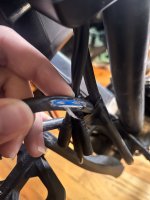
I will also add, on the biggest cable running from the PR to the motor, it seems to have touched the wheel while spinning and lost some of its insulation. I've attached a picture, but If you look close you can see that the metal from the blue wire is not touching the metal from the white wire. So unless having exposed frayed metal causes an issue, I don't think there is anything wrong with this. I think all I need to do is snip the frayed wires and wrap some electrical tape around it.IMG_6893.jpg
 
@E-HP Hi, I've opened up the motor. The hall plug's - and + go to the Controller's - and +. The hall plug's signal (white) goes to the white speed line on the controller. I measured the voltage across ground and white speed- it's 5 volts. I tried hooking up the reed switch to ground, and white speed, and the same bug occurs of throttle not activating motor until pressed fully down, then motor spinning while throttle is released.

I even tried grounding the white speed wire... It didn't fix the 5v issue.

Given this new info, anything you guys can suggest that I do next?
 
Given this new info, anything you guys can suggest that I do next?
At the very minimum, I’d replace the throttle. You may have more than one issue going on.
The throttle may get you up and running. I’m trying to recall, but I think the bbshd doesn’t need the speed input when running throttle only. EDIT: I forgot you’re using the PR, but same note applies.

On the frayed cable, any chance the frayed portion contacted the frame when you hit the bump? Is the cable shielded?
 
Last edited:
Back
Top