Spot Welding Battery Packs

I think this design is better.
I found it , in the german pedelec-forum.
Elegant and simple.
They adjust the amount of energy during the welding, by the amount of energy stored in the capacitor, by setting the voltage and size of the capacitor. Then you only need a regulated power supply, a big switch, and big wires/ electrodes to release the energy.
A big Schütz from an fork lifter worked fine. Albright SW200

https://www.youtube.com/watch?v=5TOzSjqydCY#t=14

They get good results about 1F 9-16V

Looks easy, and I think it is, but keep in mind they are working with a few hundreds Amps, “only 2-3 ms” enough for some serious damage of your eyes fingers...
So don't do it.
If you do it.
Wear safety glasses and gloves.
Do not try to “modify” something.
For example if you try thin electrodes 2mm on big wires they will explode, and liquid metal is flying all around.
Wrong polarity on the capacitor explosion?
I am not an expert.
The idea is to charge an big capacitor 1F, to about 10-16V, and use this energy to make spot welding points with Hiluminband 0.15mm.
Wires from the capacitor are? look at the video. Electrodes are 10mm!!!(because of resistance heat)
Food switch controles the Schütz.

There is one of their plans, but with mosfets for switching, and maybe to use with an ATX power supply.
I do not understand it completely, and it is not easy for me to translate.
Lamps and diodes are for protecting the ATX power supply.
There is also some kind of capacity witch is produced in the welding leads, and got to be terminated to not strike back to the mosfets? And they say do not forget about the resistance between drain and source of the mosfet about 1 mega ohm.
You better look out for one with cc/cv function.
Seems to be much more easy , if you are using a regulated power supply.

http://www.pedelecforum.de/forum/index.php?attachments/psg_einfach-jpg.54403/

Video.
Capacitor is from car hi-fi and beeps means under voltage cheap. Nothing to do with the plan.
But regulatet supply.

https://www.youtube.com/watch?feature=player_embedded&v=hg2YMafJDYA

This example seams to work good.
He ended up with an 2F capacitor, 8 IRF1404 mosfets, and adjusting the welding power by adjusting the charging voltage of the capacitor from 0-16V.
Soldering cells hurts the cells.
 
the thing with the aduio caps was done even before the thing with the car batteries. As you can read at post #1, the second option is just cheaper and you can weld quicker.

A relay wont do the job for long. As you can see, he ended up with MosFets as well...this is a dead end.

Cashew said:
I think this design is better.
I found it , in the german pedelec-forum.
Elegant and simple.

at the end of the day,you have to choose on your own what is "more elegant"
 
All the designs for DIY welders on YT use a microwave transformer modified to step the voltage down instead of up... and it seems to be a very simple design that actually works...

These designs here are not totally within reach of everyone, and it costs more... the microwave transformer designs cost zero dollars :)

https://www.youtube.com/watch?v=6fzYxcDaaI4

I am tempted to build one just because it looks so fun!!! i don't even need one that much at the moment, but it's pretty useful instead of rivets, for making battery cases, all kinds of things?!?!?

please give your advice on the biggest potential hazards of this design, once you have discharged the microwave cap and thrown it away... it didnt say what the voltage input of the transformer is? anyone know?
 
iv just been tinkering with a fat microwave transformer myself.

input voltage 240AC.

put a couple turns of thick welding lead around the secondry side, after removing the high voltage windings.

it gets really hot really quick.

melts nails etc.

havnt got stuff to stick together yet, i think the winding needs to be thicker copper and the electrodes need to be properly made, thick copper with sharp tip to concentrate the current well.

hazard would be the 240v side of the coil, but id say put the whole thing in a box...

id hoped to solder 18650's but im not too sure how much controll of heat you would have....and so will probably just end up buying a dn10 spotwelder off ebay.
 
Did any of you guys snub your mosfets? We had some trouble blowing mosfets; wonder if I should add some caps in parallel with the mosfets.
 
I've been looking up the data sheet for the IRF1324 variants. Did anyone consider using a package other than the familiar TO220 such as the wide lead AUIRF1324WL or the IRF1324S-7PPbF (D2 Pak 7 pin). These variants appear to have favourable RDSon and avalanche current figures. I have never seen them in the flesh and wonder if folks are steering clear of them because they are awkward to solder up without an industrial flow solder machine??
 
yeh Im using the IRF1324S-7PPbF and it's def. harder to solder.
 
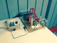
image.jpgFinished my MOT spot welder. Got a solid state relay (240v,40A) to switch the feed. Timing is taken care of by a simple 555 circuit giving 0-300 ms pulse (single) works a treat, welds are sweet, doesn't get hot no matter how fast I go! Dual switches for foot and hand are useful. Cost $70aud most of that was the SSR (shoulda got it online but couldna wait!). Electrodes are just copper wire from power cable, work well cause they don't getfatter as they slowly erode.
Does .2 ni strip with ease and .15 cu if it's slotted( with difficulty). No sparks or excessive heat. Pressure on arms is taken care of by the humble lucka ( elastic band for all the non Aussies )
I've left the transformer shunts in at this stage but may take them out at a later date if I want more power.
Hope the pic works.
 
thats impressive!

how much heat are you getting at the welds, i mean- if you do a strip ontop of wood, how much charring do you get?


I have a more or less identicle transformer kicking about, i made some breif attempts but forgot about it when we willow got a dn10.

the dn10 ended up being about the same in performance as the raw coil:lol: so im now very interested to get the transformer to work if i can.

the dn10 adjustment could possibly be improved with a dimmer switch at the supply cable, but i just havnt got round to it yet.

would love to drop bye and check it out btw! :D
 
Hell Yeah! nice one KDOGGY DOG.
 
Thanks RTL, willow
Come and have a look, any day this week is good even today. , I'll call you
Heat control is good with hardly a mark on wood just two small slight dots directly under the tips
An old welder dude told me of a trick to reduce power to cheap arc welders with only two settings ( I cant say if this is safe or effective!!) run it through 30mts of extension cord all coiled up- never tried it myself, not sure what would happen.
 
Well , iv been building a direct copy of kdogs welder, with a few little differences..

will have pics soon.

im planing on starting off with a microwave coil to get the thing working, but then using the circut to drive the huge coil in the DN10 welder we have.

this could potentially give much better controll of the huge power the DN10 has, which proved to be over the top for welding 18650.

the ultimate goal is to be able to weld copper strip. I gather this could be acheived with a very high pwered but short pulse, so this may require replacing the solid state relay with a triac or non zero point switching or continuous switching ssr, so that the pulse length isnt limited by the AC phase.

if anyonehas any ideas re. welding copper strip,or recommendations, please pipe up :D
 
Hey sunny Bro!

yeah well iv been a bit slack on the pics dept, BUT! toatally thrilled with the results whith welding the .2mm Ni coated copper you gave me. beatiful,consistent welds onto an old AA NiMH.

it was just perfect at around the midpoint of the adjustment band, with the 500k pot- stuck so that we had to tear it off with pliers but no visible signs of heat discolouration at the welds. also cool to touch immediately after the welding :D :D :D

we tried .6mm unplated copper too, very hard to get a weld on. even at max pulse length. i could get welds on it when i hammered it down to ~.3mm, especially when welding it to nickel strip.

oh, and this was all with the thick hand held electrodes from the DN10. Iv yet to try hooking up the DN10 coil to my homemade electrode setup.

will get pics up soon.

RTL
 
Hi, having followed this and schwibsi spot welding post, I've decided to have a go at building one myself.
I have some experience as an electrician and electronics student, and I've previously built one using a MOT salvaged and rewound, but it was hit and miss, and damaged a few cells! I am also in the process of building the arduino driven MOT welder on the avdweb site. http://www.avdweb.nl/arduino/hardware-interfacing/spot-welder-controller.html
I've built a dual electrode holder mechanism from an old heavy and substantially built anglepoise lamp, but I'm awaiting the power fets and the TVS diodes. I have ordered and received the irf1324 fets and driver,( it took 5 days over the weekend from ordering to receiving from Germany to the uk)! I have the cable in the workshop, and also have a couple of batteries identical to yours! I also have two 1 farad caps and a cv/cc power supply at 3-35v / 0.5-5A so will have a go at using this in the setup for portability. Is there a link to the schematic? Also I would like to include some form of adjustment to the code so that different pulse times can be dialled in, either with a pot or perhaps a 10 step digital switch connected to the digital pins on the arduino! The problem is I have absolutely zero knowledge/experience with arduino programming, I'm using these projects as my springboard, I was around in the early days of z80's and c64's, lol and I am fluent in hexadecimal! But never learned c+ etc. So if I could get some help it would be greatly appreciated. I'll start by using your circuit and code and go from there. I also have got 10 of the fets, so don't know whether it would be best to use em all for more headroom, or keep some for spares ?! Anyhow time to go and gather things in the workshop, and look forward to any replies, and help.
Regards. Dee
 
Just found this thread very cool.


just 2 12v pulses?

I think I will use an Arduino and a 12v psu and some caps.
 
I bet the amps are no where close to that. The saggy ass lead people use for the battery combined with the cables will not even allow that kind of current.

I will see what I can come up with.

My biggest surprise is the lack of caps on the JP welder boards.
 
The main point of the battery powered welder is to get away from the expensive and difficult to find and procure caps, and deal with slightly lower currents. A cap based welder normally uses a few Farads of cap, or a bit less at even higher voltage, and those caps are quite expensive (and many counterfeit caps are out there so it can be hard to buy the good stuff). The lead starting batteries with a few milliohms of load resistance can apparently put out into the low thousands of amps for a few milliseconds. In any case it seems to be enough to get good welds, and you can pick them up at the corner auto store.

Commercial welders seem to be in the 200-600 watt second range (see Sunstone for examples of commercial capacitor discharge units).

Welding successfully is done on timescales of 4-17 milliseconds with these battery based welders. One user mentions achieving 1200 amps on 8 volts of lithium batteries. You don't have to use lead. Perhaps a combo of lithium batteries and some capacitance would be a good middle ground. Not many here have used capacitor banks on their battery powered welders. If the battery holds up the cap won't help much unless it is big, and very low resistance and inductance, read expensive.

I mentioned 4k amps just to be on the safe side, if you design for 1000 amps and happen to get 2k or 3k it might not be pretty. It is hard to know exactly what folks are getting, but it appears to be more than 1000 amps. If we have 10V from the battery and 0.01 ohms system resistance we might see 1000 amps, which is 10kw, and if it lasts 10 milliseconds that is 100 watt seconds. Folks are getting good welds at considerably less than 10 milliseconds. So, the comparisons with commercial welders would seem to indicate currents in this range at this voltage are what it takes to get the job done, and they are being achieved.

This is not a motor controller, the setup and rules are a little bit different. Even an extra few inches of wire degrades the pulses (and I wonder why folks don't shorten up their cabling, it would help).

There are a lot of ways to make a battery welder that works. Your controller building experience will help you build a good welder. Just remember that the goal here is not to blow FETs or welds apart, adequate pulses are needed. Bigger pulses are not necessarily good. Good luck on your build.
 
Thanks it all makes sense.

I will look at a basic plan over the next few days.

But I mention the lack of caps because when the mosfets turn off their is a huge inductive spike.
Now because its low inductance it happens much faster but has less energy so I be the lead battery is sagging more then you suggest.

My training is as a motorcycle mechanic and I test shitty lead batteries all the time.

I have seen what 700 amps from a diesel truck will do to a pair of starting batteries and it can sag all the way to 0v if the batteries are week. But a single starting lead battery with 700 amps will typically sag to the 6-8v range. I suspect some of these diy kits work so well because the battery sags so far to stop the current from climbing to high and If I use good caps or even lithium I will need to make sure I am more careful getting it just right.

I have a few phases here I can look at using but I think the best thing to do will be design something from scratch.

Time for bed thanks again.
 
Back
Top