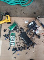
Sur-Ron - New Mid drive Bike

Offroader said:
Interesting, this is what I figured you can't trust those notches. I think there is misinformation about this as some videos say to align based on the notches.

When you did align with a straight edge did you need to use those little tension bolts to adjust the wheel?

Was your alignment pretty close to just tightening the wheel in the dropouts and using the dropouts to align the rear wheel?

Since I'm using a chain do you think I need to worry about alignment that much, or just tighten it inside the dropouts and that should be good enough? That is what I have been doing and everything seems to work out well, plus my brake caliper stays aligned every time also because it gets the wheel in the exact same spot every time.

Yes, I used the little tension bolts to adjust the axle. Things move around slightly when you tighten the axle bolt so it may take a few tries to get it spot on. With a chain, you don't need to worry about it so much. I'm not sure how it aligns when just tightening the axle bolt as you can't do this with a belt due to the belt tension.
 
I have these KITs for sale at 4000USD but every one is already taken :(
Original Case from Sur-ron for a perfect fit without mods.
72V32Ah 2304Wh (more than this simply does not fit) 20s8p Samsung 40T cells can do up to 280A.
300Amp BMS with BT

Original charger, but for 72V battery with 10A
And of course NUC 24F 20000Watt

Yeah you can get more Ah from some one else, but it will not look like this!
file.php
 
stepus said:
Hi,
thanks for DC resistance measurment, 10mOhms is what i expected. Its good for stock surron power, at constant 100Amps it will heat at 100W only on copper resistance, but for higher phase amps like 600A uphill its 3600W :D
A little update:
Mosfets have already arrived and I soldered them. It was pretty hard, i must use IR preheat, and hot air gun, classic SMD soldering air station did not have sufficient power. Now I have assembled the controller and see if it still works on surron, and hope i will finaly shunt it to BMS limit, and then shunt BMS to maximum cell current, and then shunt controller for maximum with can stock battery handle :D

I have confirmation that the litebee S is 36 fets: (not my picture) :wink:
 

Attachments

  • 193306927_10220039121836368_879188838587961602_n.jpg
    193306927_10220039121836368_879188838587961602_n.jpg
    313.6 KB · Views: 2,392
destruction.jpg
But this is classic sqare wave surron old controller, and its been already depotted earlier in this thread... in this controller there are shunt resistors on photos - also easy to shunt. But more interesting is X controller. I know of one person around which probably shorted fets on X controller, I hope controller gets to me eventually and i will depot it :D
 
stepus said:
Hi, a little update:
I succeeded shunted it ! :D
firstly i changed sensitivity from 50mV/10A (batt current 60amp, phs current +-350A) to 33mV/10A - power increased to 83A battery, and 430 phase current, so i changed it to about 25mv/10A (double of my stock power) and now i drawing about 118 battery amps, and 550 phase amps. And it drives as hell ! its whelee machine now, it do wheel spin or instant whelee from standstill :D
I will increase it to about 125 battery amps, and must do shunt BMS, now i get er - 119 on display which is overcurrent fault, or BMS cuts me in a long hill when i run full throttle...
I thing controller can handle even more amps, but stock battery limits me, there is only 11 cells paralel and each cell is 10Amps continous discharge... And i dont want to damage it.
Later i will maybe post some youtube video how to do, and with results.

edit: Does anyone know how much battery current is drawing ASI BAC / NUCULAR on stock surron battery with BMS mod bypass ?

This is great! It looks like you increased current by moving the flux rings, rather than bending the hall sensors at an angle, as others have done previously. Seems like a good idea. Though, you might be able to bend the hall sensors without removing all the potting, just a tiny bit of potting around the sensors themselves. If anyone is interested in a slightly easier mod. Although, it sounds like just opening the case is the hard part...
 
Yes, i offseted flux rings, to lower sensitivity of halls. Bending halls is also possible, but you need to set accurate sensitivity on both halls, and when you bend halls 4th time you can easily broke legs :D or you can put some ferrite rings on halls - it will also lower flux flowing through hall.
I thing opening cover can be easily done by unscrew all screws, and put some pry tool between the aluminum heatsink and the cover and put it in owen. But i dont know if plastic cover, wires and connectors will survive 100C temp without any damage...
 
stepus said:
Yes, i offseted flux rings, to lower sensitivity of halls. Bending halls is also possible, but you need to set accurate sensitivity on both halls, and when you bend halls 4th time you can easily broke legs :D or you can put some ferrite rings on halls - it will also lower flux flowing through hall.
I thing opening cover can be easily done by unscrew all screws, and put some pry tool between the aluminum heatsink and the cover and put it in owen. But i dont know if plastic cover, wires and connectors will survive 100C temp without any damage...

Ferrite rings on the halls sounds like a good idea. It should be easy to keep them both matched and shouldn't require as much depoting.
 
Hey everyone, had my sur-ron stolen from a gated garage this weekend. In the Austin Texas area, here’s a post about it.

Keep an eye out for anyone trying to buy a charger or new ignition.

$1000 reward to anyone that locates it.

https://www.facebook.com/bennett.staley/posts/157034949808080
 
More Asia electric M/C are showing up, there is a nice dirt bike seen @11:00 min this vid
https://www.youtube.com/watch?v=0GqbBBNeXH0
 
X-Nitro said:
More Asia electric M/C are showing up, there is a nice dirt bike seen @11:00 min this vid
https://www.youtube.com/watch?v=0GqbBBNeXH0

that's the Time et / kollter banshee;)

https://endless-sphere.com/forums/viewtopic.php?f=10&t=111293
 
I'm going to bite on that time moto. I've been waiting too long for the storm bee. Suspension looks iffy and the welds aren't great, but should hold up fine. Got a price quote of $3800 shipped to the U.S. Month wait time to ship and probably 3 weeks to get here. That puts it in September likely.
 
dirkdiggler said:
I'm going to bite on that time moto. I've been waiting too long for the storm bee. Suspension looks iffy and the welds aren't great, but should hold up fine. Got a price quote of $3800 shipped to the U.S. Month wait time to ship and probably 3 weeks to get here. That puts it in September likely.

Where were you quoted that?
 
Just to throw it out there, if anyone is looking for a budget Sur-Ron brake upgrade, Shimano MT520 works well, it's a 4 piston.

I got a good deal on MT520 calipers so I just swapped those and the brakes are better now, more feel and power and they don't overheat where they used to.

MT520 is also super easy to install and bleed.

And for more overheat protection, regardless of which brakes you use, I suggest ceramic brake pads and big Magura MDR-P rotors.
 
I have a 60V Su-Ron battery that I want to use for another project. I see it has an RS-485 port for BMS communication. Has anyone been able to crack the RS-485 protocol and communicate with the BMS?

20210709_104347.jpg
 
Hi,I did not sniff the communication, but my friend do. I planning to connect to it via arduino, and print on LCD :current,cell voltages, temperatures, etc. BMS can be also reconfigured, my friend has config files where he can do changes and then send it to BMS. He increased current limit in my battery from 95A to 125A. So my BMS is fully working and its safer than bypass and still fully working coulomb meter (percentage LCD) :D. I did shunt mod to my controller so i needed to modify battery for bigger current.
 
That's interesting, do you think you could find out what message needs to be sent to request basic info from The BMS?
 
stepus said:
I finally made that video about shunting the controller :D
[youtube]kjQT7CpUh-M[/youtube]
and some hi quality photos :

So would it not be easier to just replace the magnets with either a smaller or larger gap. once we have that info everyone can do it. Right now it would be pretty tough for most of us to move them to the right place.
 
Hi, its not magnets, its iron core to "catch" magnetic field aroud terminal, and direct it through hall sensor. And yes, it will be easier to find similiar material ring, and cut in it larger gap - then i thing it dont need calibration like i do. But we still dont know if stock controller is 24fet like mine was, or its 36fet - so it can be modifed to currents i have.
Controller didnt blow up yet :D, so i thing 125A is OK for it.
 
MOTOR Detective! :twisted:
After i watched a video from "Electrified clahllenge" that was showing the magnet replacement on a Motenergy ME1718 I found that this motor was pretty similar to the Sur ron motor in many way! https://www.youtube.com/watch?v=C3vieYw6rBc&t=84s

Motenergy were making various motor for Zero motorcycle and i know that there are some varient of the 75-7 motor like the ME1507 and that it is the same factory that were making both if i remember correctly.

Maybe Motenergy could also be the Sur ron manufacture? Both ME1718 have the same number of poles, same rotor design, very similar stator design and motor extruded casing....

So maybe for these that run it accidently at 14krpm and have magnets flying appart you can get magnet from motenergy.
sur ron compare to me1718.jpg
 
Depending on the diameter, maybe it would be possible to make a liquid cooled version of the Sur ron better for the BAC8000 72V users.!

I contacted Motenergy to know about possibility to buy parts.

Maybe it is also possible to use the ME1718 instead of the stock motor. remember that the sur ron motor has spacers to fit in the frame. maybe there is enough room for that :wink: The ME1718 has more stator and rotor width. Taking the Sur ron motor side covers and fiting these to the ME1718 stator as well as modifying the shaft to match the sur ron pulley... it could work ? :)

Doc
 
similar mounting holes too: https://www.kit-elec-shop.com/17817-large_default/synchronous-motor-me1718-pmsm-brushless-ip65-6kw-sin-cos.jpg

synchronous-motor-me1718-pmsm-brushless-ip65-6kw-sin-cos.jpg
 
Me1718 specs:

https://www.kit-elec-shop.com/gb/sy...r-me1718-pmsm-brushless-ip65-6kw-sin-cos.html

Its nominal power is 6 kW for a nominal speed of 4000 rpm.
This ME 1718 motor is a brushless motor, so it doesn't need any maintenance, it is also called PMSM brushless.
It is a three-phase permanent magnet synchronous motor with axial air gap.
The ME1718 motor has an efficiency of 88% for DC voltages between 36V and 60V DC.
It is a 5-pole (10 magnets) motor.
The direct current is 120 amps for a voltage of 60V DC.
Its permanent output power is 6 kW at a voltage of 60 VDC.
The maximum rotor speed is 5500 rpm.
The winding has xx turns per phase.
Its resistance between phases is between 5.06 and 5.28 milli Ohms.
The inductance between phases measured at 1000 Hz is between 39 and 43.5 micro Henry.
Its mass is 13 kg.
It has a temperature sensor equivalent to KTY84-130 and a sin/cos type position encoder.
This ME1718 motor is waterproof and is IP65.
Explanations of the terms CW (ClockWise): clockwise and CCW (Counter ClockWise): counterclockwise.


IMPORTANT The ME1718 is the Sin/COS version and the ME1719 is the UVW ( hall sensor version)


Direct Manufacture: http://en.jintankm.com/intro/32.html

Motor dimensions: https://www.kit-elec-shop.com/gb/index.php?controller=attachment&id_attachment=787
Motor performance curves: https://www.kit-elec-shop.com/gb/index.php?controller=attachment&id_attachment=788


motor supplier confirmed to be Jintan.PNG


One of the supplier: https://www.miromax.lt/en/m-6/c-39/...ali_power_48kw72kw____64ag97ag___240cm3360cm3
 

Attachments

  • me1718 and 1719 full spec.PNG
    me1718 and 1719 full spec.PNG
    96.5 KB · Views: 3,236
Back
Top