Suzuki DR650 40kW mid conversion

Mugenski

10 W
Joined
Aug 2, 2015
Messages
81
Location
Ontario
Hey all and welcome to the build thread for my post '96 DR650. This conversion has been an idea in my head for almost as long as I have owned the bike. I told myself that when the engine gives out the bike will get a new life in the form of a conversion. Progress thus far has consisted of stripping the bike of it's petrol burning components and honestly a lot of staring at where I need to fit a motor.

Here are a few of my targets and potential hardware considerations for the build.
Weight: Under 175kg. This is equal to it's petrol setup with a full tank
Power: 15kW cont, 40kW for 30s. Peak 80kW.
Capacity: 12-15kwh of pouched NMC. Possibly 73Ah Farasis pouches.
Regenerative abilities via regen lever in replacement of the clutch lever.
Controllers, looking for something around 100v with 300-400 battery amps and 800-1000 phase amps.
Motors under consideration are Zero 75-7(r) and the QS180.


As the bike sits with engine removed I have about 90kg to meet my target weight. I figure 70kg of battery with the rest going to the motor and controller. This isn't a hard limit but I would like the bike to ride and feel as it did before. The 30s power level is about 20% more than a standard gas burning DR. I don't suspect the cush hub and drive-line will have issues with that power level. Peak power may cause issues including relocating the front wheel closer to the sun. I would like this project to end up as clean as possible. I've seen some controllers that offer stepdowns like the 3shul. That interests me as it reduces component count and keeps the build clean and lean. I know I'm going to have a challenge in fitting that much battery.

I thank all who have already contributed their collective knowledge and I look forward to spending many hours reading. Advice regarding motor, controller, contactor and BMS is much encouraged. I am looking to source a motor as soon as possible as I feel that it's location (and hopefully no requirement for a jackshaft!) is crucial to getting on with the rest of the build.

If you read this far with no enticing photos then many thanks from me.

-Mug
 
Last edited:
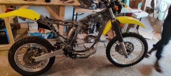
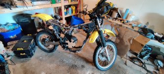
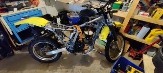
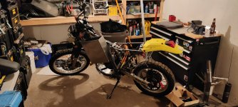
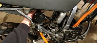
Here is where we are starting from. If it wasn't for a gracious friend and their loaning of time and space this project would still be on the back burner. You can see the cardboard aided QS180 sitting in the frame in the second photo. It looks like the chain line won't be an issue. Perhaps a little extra slack but nothing unreasonable.
IMG_20230908_095723.jpg
I'm leaning quite a bit towards the 3shul CL1000. I've jumped mentally between the fardriver and 3shul several times. Planning at the moment to run it with 30s. Reason for the 3shul is hopefully better documentation being open source as well as variable regen. Is it unwise to run regen when running at a controllers maximum? I'm not looking to pop FETs but I have struggled to find motors and controllers well suited to this size build. The shul does look like it will fit almost perfectly under the seat where the airbox and CDI use to reside. Score.
IMG_20230908_120326.jpg

There is a Zero 75-7 done in cardboard as well that can be seen in the background. It was decided that the QS would fit better. The smaller diameter of the QS is going to leave more room for battery. As it sits a 30s pouch should fit along the downtube. That accounts for about 8kWh. The second group is going to be split in half and it should tuck in above the motor. The acerbis tank is going to get gutted and remain as a shell in its usual spot. This will cover the contactor location (triangular space at down/top tube) and tuck away a good portion of the battery from sight. I have no issue with this bike maintaining some of its ICE'd vibe.

Time to put the motor on order. I am slightly worried that Damon says the motor has to go to production as they don't keep any stock of the QS180. He claims 2 weeks production and 5 days shipping. I'm doubtful but without many other options.

I'll get better with the documentation and photos as we go. Thanks for reading along.

-Mug
 
Last edited:
I do not know if the QS180 xan put out 80kw. If it will do 50kw it will be still very good.
I'm still wanting to see some dyno runs of this motor.

The Fardriver 72680 in my scooter runs very good with throotle regen and weakening field and 21S NMC-Pouches charged up to 87,5V. I could easily draw 300A from the battery but my hub-motor overheats to fast.

It has a fully variable regen set with the release angle and releasw speed of the throttle. Not as good as an extra variable regen input but it works very good on the road.
For off-road use a second input will be a lot better.
 
That drag bike video on the other post says 108v @ 1000amps = 108kw
I would like to see the motor temps after that 10.2 seconds in the 1/4 mile run.

So it seems that you might be able to peak at 80 kW if that drag bike specs are true. But who knows the details of his motor it could be modded, or somehow water cooled or something.

j bjork

Has been using the QS 180 so maybe he has some insight on possible peak power levels.
 
Here are a few of my targets and potential hardware considerations for the build.
Weight: Under 175kg. This is equal to it's petrol setup with a full tank
Power: 15kW cont, 40kW for 30s. Peak 80kW.
Capacity: 12-15kwh of pouched NMC. Possibly 73Ah Farasis pouches.
Regenerative abilities via regen lever in replacement of the clutch lever.
Controllers, looking for something around 100v with 300-400 battery amps and 800-1000 phase amps.
Motors under consideration are Zero 75-7(r) and the QS180.
I dont know what the qs180 90h are capable of, but it will for sure not give 80Kw output with 30-40Kw input (100V 300-400A)
To get 80Kw output you will probably need over 100Kw in, that is over 1000A at 100V, and at those current levels your battery will probably not deliver 100V.
 
I dont know what the qs180 90h are capable of, but it will for sure not give 80Kw output with 30-40Kw input (100V 300-400A)
To get 80Kw output you will probably need over 100Kw in, that is over 1000A at 100V, and at those current levels your battery will probably not deliver 100V.
I was likely thinking in hp when I wrote 80kW. I started by speccing the battery to be capable of twice the ICE output figuring whatever results from that will be fast enough. Running the system at 40-45kW would still net me a gain over the ICE version as well as keeping the batteries happy by never exceeding their rated continuous discharge. Their max discharge is around 70kW minus of course their own internal heating losses, controller, motor and chain as well. Still plenty any way I dice it.

The real curiosity here is the power level this motor can sustain. I think there is a lot left on the table until a water jacketed or gearboxed QS180 comes around.
 
Last edited:
As the more seasoned builders know analysis paralysis is a real time killer. That said the bike hasn't stalled out as much has been accomplished in my understanding of several of the larger hurdles.

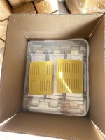
Let's see where we are now. The less than standard m12-1.5mm bolts have been ordered. It seems I fumbled somewhere along the line and was expecting a more common m10 thread and pitch. Some crude bracketry has been cobbled together to get the motor sitting close to it's final home. When I am happy with the chainline and battery box placement I will be ordering out for some nice stainless plate to mount the motor. In that vein I have had to re-familiarize myself with Fusion360. Oh I didn't mention, the motor has arrived!

Motorin.jpg

I am quite pleased with it's dimensions relative to the frame. I think in the future this motor could be a very easy drop in replacement for the DR if the manufacturer adopts a few changes to the motor housing. I have seen this done on other smaller QS motors. I suspect they just need someone to supply those dimensions. The plan is to keep a shell of a tank on the bike for that bushpig aesthetic.

Motortank.jpg

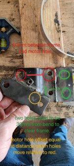
The unfortunate bracket on the outside of the frame is temporary. A modified stock engine bracket will take it's place mounted from the inside of the frame. The 30mm mentioned dimension should be something closer to 36mm if anyone ever decides to tackle a similar conversion. The photo was initially just a reminder for myself so I apologies if it's not clear. The bracket gets extended and flipped. The yellow denotes the new motor mount hole required and green the shifted frame mounts. The reason for reusing this bracket is simply that I don't have access to a brake press to bend a new one. If you're ever going to attempt to drill on or near a weld bead it's a good idea to heat the part glowing and cool it slowly to lower the hardness along the bead. Barring that a carbide endmill can tackle a weld.

bracket modification.jpg

60pcs of 76ah farasis are on their way. I don't expect to fit that many but I do expect china to send some duds even after requesting capacity tested and matched cells. A realistic configuration is closer to 26s2p. I did have nickle tabs welded on but I am not expecting to solder. I had thought a pulsed TIG tack would be alright but have decided against that after more reading here on ES. I am tossing around the idea of flat head washer rivets, blind rivets and rivnuts. Rivnuts would facilitate my series connections with copper bars and bolts. I'm leaning toward 1awg (50mm2) wire to the controller.

cells.jpg

I was planning on a CL1400 but after talking to hackey he said to wait another couple weeks and contact him again. I'm not sure what's coming down the pipe but he's working on something (as are Tronic and Trampa too).

Not pictured yet is the mocked up battery box. While I started with 1/8th aluminum I have been considering a switch to 14 or 16 gauge stainless. My concern is susceptibility to cracking in the weld and heat affected zone. Welding will be much easier with the stainless however the downside is the weight. Input here is welcomed.

Some other rather uninteresting components have been put on order such as a relay BMS and dominio throttle. Domino is the IP67 pot version but after ordering I heard wind of hall based throttle sensors. Perhaps that is a safter option?

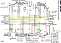
While I wait for stuff to arrive I have begun working from an annotated DR650 wiring schematic I found on the DRRiders forums. I figure since I have the harness I may as well put it to use. Currently I am working on which switches and indicator lights will be retasked from ICE useage. I was thinking of wiring the ICE killswitch to the main contactor relay wires as an estop and the neutral light as a power on indicator that the main contactor is closed. BMS should handle the pre and discharge relays with a timer removing the possibility of popping a controller with inrush current should the user miss-step. I'm also not sure if the 12V for the BMS is simply for the contactors or if it is required for the BMS to balance when the rest of the system is powered off.

DR annotated coloured wiring diagram jpg.jpg

This looks reasonably straightforward except I'm slightly confused as to how the Br and Gr is getting power when ignition is in Run instead of P. Might require investigation with a meter when I am next at the bike. I'd like to use ignition park as charge mode. The key can be removed in this position so the ignition/controller could be locked out while still retaining the ability to charge.

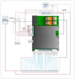
The BMS is not the CAN variety. I figured at a later date I can switch over to something like the ennoid if CAN requirements and budget allow. My thoughts on the predischarge relay is that I won't need anything like a contactor for the low amperage but simply something that can handle the voltage and a few amps should suffice. Similar for the charging relay. I don't really like the loss of space for 3 independant contactors if there is a cleaner/smaller option.

Ant wiring.jpg

Any advice or opinions are welcome and I apologize if some of my questions would be better off in the another forum section. Hopefully my inclusion of a few photos buys me some leeway 🙃
Cheers
 
Last edited:
I was planning on a CL1400 but after talking to hackey he said to wait another couple weeks and contact him again. I'm not sure what's coming down the pipe but he's working on something (as are Tronic and Trampa too).

Not pictured yet is the mocked up battery box. While I started with 1/8th aluminum I have been considering a switch to 14 or 16 gauge stainless. My concern is susceptibility to cracking in the weld and heat affected zone. Welding will be much easier with the stainless however the downside is the weight. Input here is welcomed.
Did Hackey say that there was something new to be released soon, or was it just that they didnt have any cl1400 for a few weeks?

I prefer to weld alu compared to stainless, It is such a pain to keep the back of the weld free from air when welding stainless (dont know what it is called in English)
 
Did Hackey say that there was something new to be released soon, or was it just that they didnt have any cl1400 for a few weeks?

I prefer to weld alu compared to stainless, It is such a pain to keep the back of the weld free from air when welding stainless (dont know what it is called in English)
Hackey said improvements of some kind. Specifically I had asked about buying stateside from alienrides. Perhaps he just wants all the profit but we'll see in another week or two.

Regarding backpurge in stainless. For openroot sure but I don't think it's needed for this application. I've certainly never backpurged for other stainless stuff I've made for my gas bikes like tube pannier racks. I suppose more effort can be put into welding the aluminum first, plenty of material to work with. The weight savings is also somewhat significant.

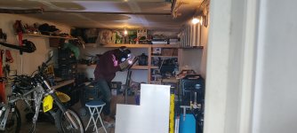
Speaking of open roots here's my gracious shop host getting in a little practice.

IMG_20231014_144903.jpg
 
I figured it's time for another update (Let me be honest - I have hidden a question in here for the more experienced...)

The cell count has been modified. While the initial plan was to go with a 30S2P pack, physical restrictions and factors such as wind resistance and symmetry between both pack halves were discussed. A 24S2P configuration seems best attainable. While it is a significant reduction in capacity, after all things are considered I think it's a safer and more attainable goal. I also think it will prove to be better aesthetically while remaining weight conscious. Usable capacity of 30S2P was calculated at 13.5kWh with 10% held off both top and bottom of the pack. With a 24S2P we are now looking a little under 11kWh.

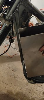
Details and dimensions relating to the battery and boxes have been firmed up. My partner in crime made a great point relating to aluminum vs stainless battery boxes. The stainless is going to hold onto much more heat from the battery. Debateably better in the winter months but definitely a no go in the summer months when the bike will be ridden most. Aluminum it is. After mocking up a 13x15" aluminum box it seems that the packs will ride side saddle instead of in a horizontal fashion behind the downtube. Reasoning is simple, there is less surface area in the wind as well as leaving a better airflow path for both the motor and controller to breathe. This is a tight but manageable fit. Full lock maintained even if it's a little bulky looking. Function over form for the mighty bushpig.

IMG_20231115_185211.jpg

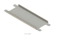
I drew up a battery tray to help draw heat from the parallel groups to the shell of the battery box. While I don't expect to often draw into the packs burst current abilities, I did do some quick calculations on the waste heat at those amps. It's in the range of 1500w per box. These 1mm aluminum trays will also provide a way to index the cells with threaded rod. The rods will be used to provide the needed compression. Double-sided tape will keep the cells stuck to each other and the trays. Trays will go between every parallel group, I think it's overkill to put one between each cell. I'm also investigating 3D printed end covers for the cells and trays. While all the auto manufacturers (thanks to Munro Live for the teardowns) have injection moulded cell trays, I was unable to find a way to procure any. On the plus side Farasis energy did at least respond to my email inquiry.

Battery cooling tray fusion.jpg

Cell connections will likely be made with two 1/8" blind copper rivets, a rivnut to facilitate bolted series connections and some anti-ox paste. Copper washers may be used with the blind rivets to get a little more surface area and meet the minimum clamping thickness of the rivets. I do worry slightly about the rivets working loose. I know others have utilized the method but I have also seen Tesla's issues with blind rivets utilized in early vehicles to hold BMS connections and them working loose over time.

Now I am a man of conviction when it comes to meeting my own goals. Both the 26S2P and 24S2P packs are under my 12kWh usable target. My limiting factor for the size of the battery box in the vertical dimension is the motor on the bottom and the forks on the topside. Upon further inspection with the shock removed, it seems the motor is sitting 11mm high relative to the ICE sprocket and chainline location. I think we can massage that a bit and gain a little more vertical space. The other option would be to limit the steering head angle to stop contact with a taller battery box. I've ridden this bike for long enough to learn full lock in parking lots, I don't want to give that up. Problems, problems, problems.

IMG_20231121_180839.jpg

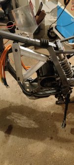
My laser cut brackets have arrived. I considered them prototype as I didn't spend a lot of time getting the measurements accurate. To my surprise I was only off by a couple mm. For the time being they will work. For gen2 brackets I have tweaked the design to allow more space for the battery box as well as a slight improvement to the chainline by lowering the motor. The motor sits about 60mm forward of the ICE sprocket location and the CS sprocket is 10mm smaller in diameter than stock (15T down to a 13T). Perhaps the saving grace here will be the 53T rear sprocket diameter has increased by 60mm over the stock 41T. Trig is not my strong suit. Thankfully Suzuki has provided a nice full wrap swingarm guard so I will be keeping an eye on any potentials there. It was noted that there was quite a bit of wear on the underside of the guard from the ICE setup. I guess 70k km with lots of engine braking will do that. Below is a photo of the motor in the Gen1 brackets along with the startings of the battery mounting frame. The C channel will nest into channel welded to the back of the battery boxes.

IMG_20231121_180729.jpg

Sent Hackey a followup message a few days ago. Haven't heard back. No worries either way as there is a high amp Tronic coming down the pipe. Trampa also has the STR-500A which looks like it had some real thought put into it. Lots of IO, replaceable boards and connectors internal to the housing. It's just a shame its 22S rated. With a depleted 22S pack at 3.5v/cell I would still be able to maintain highway speed however my usable capacity drops even further to under 10kWh... Maybe it won't matter so much with a J1772 charging option.

IMG_20231115_184616.jpg

I have located some suitable fuses from mouser. 125VDC 500A. I would like something closer to 650A but these are clean in form and appropriately rated voltage wise. Since these fuses are relatively new there aren't many options for fuse blocks. I am thinking some could be made out of 3/8" G10.

Speaking of eletrical saftey... I want to power the stock ICE harness from a DC-DC stepdown fed into the stock connections where the lead acid was. I will also have 12v available from the controller. Which is a better option for my DC-DC stepdown, isolated or non? I ask because I don't have all the wiring details (or knowledge) ironed out in my head yet. I would like the option to use both the DC-DC and the controller 12v supply. Will I run into grounding issues between those two circuts or in supplying the BMS? I learned a tough lesson years past when I shorted a floating 12v DC ground to a grounded AC panel. That mistake still haunts me so I figured it would be good to get some advice where I am deficient. I understand I will pay more for an isolated supply but I feel putting a budget on safety aspects would be foolish.

Lastly I am really over analyzing my HV connectors. Part of me wants to use readily available anderson connectors. The other half of me screams that it's not IP rated and I should be using something a little more robust on the off chance I get caught in a little rain. Perhaps the answer is anderson connectors inside an IP rated electrical enclosure? Other ideas?

That's all for now.
 

Attachments

  • IMG_20231121_180849.jpg
    IMG_20231121_180849.jpg
    1.7 MB · Views: 11
  • IMG_20231115_184642.jpg
    IMG_20231115_184642.jpg
    1.8 MB · Views: 13
My Anderson SB50s (and 45s) under the SB Cruiser trike have been soaked from splash (many times) and directly submerged in flash flood waters (at least twice), and the dielectric grease I use on them has yet to fail and allow connection faults. Doesn't mean they won't, but they haven't yet, in the years it's been wired up with them (since 2018? I forget when I put them on there).

For the DC-DC, isolation means that your grounds for traction and 12v would be isolated from each other, rather than connected. This has some consequences, in that you cannot connect the 12v system to do anything with the traction system, because to do that you must connect the grounds together. If you require the ability to do that, you might as well just use a non-isolated unit, as there isn't any point to isolating the grounds if you're bypassing that isolation anyway. ;)
 
Back
Top