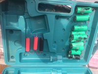
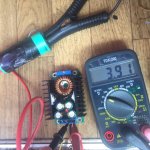
I have included pics of the buck CCCV charging a cell with red light on set at about .6 amps and set point at 4.2V; now reading 3.9V
and the other cells are resting in parallel balance config, the red wires on the positive side are soldered to the existing nickel tabs and pulled out so the dont touch the sides. Had that happen once with some not so good results. maybe latter I will make some plastic cut outs and hot glue them on the pos side for extra protection
Every pack has an Ah capacity, please answer my question. If you can't figure it out tell me your xPyS layout and link to the new "basic"cells.
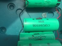
I threw away the cover for the pack, but I remember it at 12 Amp hours. these cells arent new. Got them for free. Trashed the ones under 3.7 volts, charged the other ones to 4.2. there are ten of the green ones. Have included a pic of their model #. What is xPyS layout? The red cells (18650) are for my light set (12 volts) the green ones are for my motor (36 volts in series, for now) no range but its all I have right now. specs for the panasonic CGR26650 B are as follows:
--------------------------------------------------------------------------------------------------------------------------------------------------------------
3300mAh
Nominal Voltage:
3.7V
Type:
Li-polymer
Voltage:
3.7V
Application:
E-bike,Computer ,Mouse,Battery pack,etc
Color:
Light Green
Warranty:
1 Year
Capacity:
3300 MAh
Battery type:
26650 Rechargeable Li-ion
Cycle life:
1000 Times
Material:
Lihtium Polymer
--------------------------------------------------------------------------------------------------------------------------------------------------------------
A logger that lets you plot the curves on your PC would be ideal.
anywhere I can get one of these or make one...got some spare nano arduinos and use the serial monitor, so something like this?
When did the light go to red? At the CC to CV transition? Some time later, at a certain amps rate, or perhaps based on just a timer after that?
red to blue occus at 4.2V
Could you link to the unit you're using?
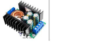
I posted a pic below of the model and company mfg. specs/instructions follow:
Description:
the maximum current is 8-9A
(Spot: the maximum current is 8-9A, the input voltage is the highest 40V output voltage is about 35V or so)
(Due to 12A current chip manufacturers to stop production, replace the chip current from the previous 12A down to 8A current (actual test maximum current in 9A or so), the input voltage from the previous 32V to 40V, the output voltage from the previous 28V to 35V. Power supply for 10 strings of high power LEDs 12A chips are subject to change.
QS-2405CCBD-12A power supply module
Size: 65 (L) * 47 (W) * 23.5 (H) mm
typical application:
Adjustable power supply (12A power is large enough), high power LED driver, LED display driver, lead battery charging, lithium battery charging, car power, car notebook power supply (buck), power supply, low voltage system power supply (such as children Toy car with 12V battery buck to 6V), 24V to 12V 12A \\ 12V to 5V 12A \\ 24V to 5V 12A \\ 24V to 19V20V and so on, the application range is very wide.
1. Fixed turn lamp current is 0.1 times the constant current value (used when charging to identify whether the battery is full);
2. Using a dedicated reference IC, and high-precision sampling resistor, so that constant current more stable, (20 degrees to 60 degrees constant current 5A when the temperature drift less than 5%). Especially for LED driver
3. Output current, the maximum output current can reach 12A, to meet most of the needs.
4.4 high-frequency capacitors, effectively reduce the output ripple, improve work stability
5. Double heat sink design, MOS tube Schottky diode independent heat sink, heat is good, do not affect each other
6. At the cost of large-size iron-silicon magnetic ring, improve work efficiency, and with pure copper and Rao, reduce heat, improve efficiency.
7.3296 multi-turn potentiometer, voltage and current regulation of high precision, good stability.
8. Special current sampling resistance Current sampling accuracy High stability and good temperature drift small. LED essential.
9. Two-color indicator light, working status at a glance. Charging must be.
10. Voltage and current are adjustable, so adjustable power supply effect, 12A current, power enough.
Module parameters
Modular nature: non-isolated step-down constant current, constant voltage module (CC CV) charging module
Applications: High-power LED constant current drive, lithium battery charging (including ferroelectric), 4V, 6V, 12V, 14V, 24V battery charging, nickel-cadmium nickel-metal hydride batteries (battery pack) charging, solar panels, wind turbines
Input voltage: 7-32V (without constant current 5-32V)
Output voltage: (1) continuously adjustable (0.8-28V)
(2) fixed output (0.8-28V between any choice), please tell the treasurer when buying. (For the time being only for bulk customers, all the sample adjustable type)
(3) If you need higher voltage please contact me directly
Output current: up to 12A (power tube temperature exceeds 65 degrees please add fan cooling, 24V to 12V 6A or less open environment generally can not fan)
Constant current range: 0.2-12A (adjustable) (no constant current without this function)
Turn current: constant current value * (0.1), turn the lamp current and constant current value linkage, such as the constant current value of 3A, turn the lamp current is set to constant current 0.1 times (0.1 * 3A = 0.3A), when the constant When the flow rate is adjusted to 2A, the turn lamp current is 0.1 times the constant current (0.1 * 2A = 0.2A).
The secondary version is fixed for 0.1 times (the actual turn lamp current is probably not very accurate) is used to charge if the fill is full of instructions.
Minimum pressure difference: 1V
Output power: maximum power of about 300W, power tube temperature over 65 degrees please add fan.
Conversion efficiency: up to about 95% (the higher the output voltage, the higher the efficiency)
Operating frequency: 300KHZ
Output ripple: 20M bandwidth (for reference only)
Input 24V output 12V 5A ripple 50mV or so (no noise)
Operating temperature: industrial grade (-40 ℃ to +85 ℃) (the actual use, please pay attention to the power tube temperature, the temperature is too high, please strengthen the heat)
No-load current: typical 20mA (24V to 12V)
Load regulation: ± 1% (constant voltage)
Voltage regulation: ± 1%
Constant current accuracy and temperature: the actual test, the module temperature from 25 degrees to 60 degrees, constant current value of less than 5% (constant current value of 5A)
Dynamic response speed: 5% 200uS
Potentiometer adjustment direction: clockwise (increase), counterclockwise (reduced) close to the input potentiometer for voltage regulation (CV), close to the output of the potentiometer for the current regulation (CC)
Indicator light: two-color indicator light, red light in charge, charging complete indicator green (no load is green) without constant current indicator light is red.
Output short circuit protection: Yes, constant current (current set constant current value)
Input Reverse Protection: None,
Output to prevent backflow: none.
Wiring method: terminal block
Battery charging method:
1. Make sure you need to recharge the battery's float voltage and charge current, the module's input voltage;
2. Adjust the constant voltage potentiometer, adjust the output voltage to about 5V.
3. With the multimeter 10A current block measurement output short-circuit current, while adjusting the constant current potentiometer so that the output current reaches a predetermined charge current value;
4. Adjust the constant voltage potentiometer so that the output voltage reaches the float voltage;
5. Connect the battery, try charging.
(1, 2, 3, 4 steps for the module input power supply, the output is not connected to the battery.)
LED constant current drive use:
1. Make sure you need to drive the LED's operating current and the maximum operating voltage;
2. Adjust the constant voltage potentiometer, adjust the output voltage to about 5V.
3. With the multimeter 10A current block measurement output short-circuit current, while adjusting the constant current potentiometer so that the output current to a predetermined LED operating current;
4. Adjust the constant voltage potentiometer to make the output voltage to LED maximum operating voltage;
5. Connect the LED, test machine.
(1, 2, 3, 4 steps for the module input power supply, the output no load LED lights.)
Package Included:
1 x DC-DC CC CV Buck Converter Step-down Power Module 7-32V to 0.8-28V 12A 300W USA