LightningRods
1 MW
I replaced the image links as attachments. You should see everything now.
LightningRods said:nicobie said:Maybe it's just me, but I'm not seeing the pics.
I’m seeing them. Not sure what could be causing the issue.

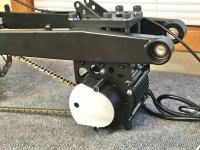
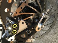
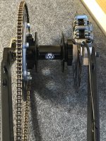
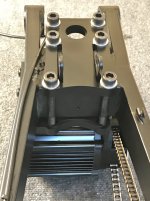
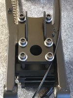
Pic 6 above, rear top view, the space between disc and swingarm where the caliper bracket mounts to the swingarm, that looks like a sleeve spacer on the axle. So I would simply make the caliper mount plate pivot on the axle where that space is (extent plate down to over the axle with a through hole) and slot the bracket over one of those bolt holes with a socket cap screw fastened from the inside of the swingarm to act as an anti-rotation pin, probably the higher of the 2 holes for less stress. Ideally even, I'd make the caliper mount plate fit over that spacer and then weld the plate to the spacer for a much stronger bracket torsionally, bit more complex but for the quality, performance and reliability of your systems it seems more appropriate to me.LightningRods said:A solid mount is safe and won’t slip under use. I’m open to suggestions for an adjustable caliper mount.
That sounds like sound logic sir and I didn't mean to disapprove the design you have, it looks very robust and reliable. I was thinking aloud. KISS right [emoji6]LightningRods said:No this is certainly not an issue of safety. What I did NOT want was a complicated system that could come apart and disable the rear brake or far worse jam the wheel. I trusted the Qulbix basic design and made it thicker and from better material.
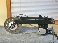
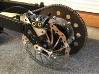
The pads are properly positioned when the chain is new. The chain should be replaced after either 1% or 2% stretch, depending on how cautious you are. With this drive’s center to center distance of 15.76” we’re talking about wheel movement of .157” at 1% and .315” at 2%. 1% stretch is going to have no effect on the brakes and at 2% the top left corner of the pad might start to move off of the rotor. So a slight loss of braking area. Someone who was really concerned about this effect could swap out the rear sprocket for one with a couple more teeth and move the wheel right back where it was.
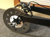
Another simple way to reposition the pads as the drive chain stretches is to lower the caliper straight down. This could be done by having the main billet mount shorter by the amount desired for correct pad placement when the chain has stretched. A thin spacer would be used when the chain is new. This method is simple, inexpensive and can’t slip or come apart.