Erogo
100 W
Man, sometimes I wish I had more skills. And forethought. Skills and forethought. Like last night, when I hit the go button, and everything flew apart. Stink.
So I've been building up this drive for our baby trailer.

We've got a real steep driveway, and when the mama gets home with the bubba, 16 degrees of concrete slab just looks a bit much. (That turns out to be 35% gradient, for those who prefer to think in centimal). Some form of assistance was needed.
I thought for a while about rigging up a cable with a pulley and a switch and a controller, and it just seemed a bit fraught. How to stop the other people from activating it, how to reset it for another haul up the hill etc. Onboard propulsion was needed.
I was vaguely aware that electric motors span quickly, and would need gearing down. Maybe these would do?

I probably thought about them for a wee while, read about the robot people, read about locking out the torque limiter... I guess they might do something, but then somehow I came across the 'sphere, the joys and promise of brushless, of lithium polymers, of ESCs, BECs, STs and HKs. Awesome.
I was still thinking the electric drill gearbox might be a starter, one of those ones in the picture is made out of real Metal. But then, I remembered the winch that I'd salvaged from work, and had thought about setting up as a sort of ropetow on the driveway. Wondered what sort of gearbox was in that puppy, cause surely winches handle grunty power and torque... sure enough, it's a metal planetary gearbox, with a 100:1 reduction. Perfect for the eventual operator, who had expressed a powerful disinterest in firing the bubba up the driveway at anything greater than a moderate pace.
View attachment 3
So, some calculations and mathematics, and it all appeared to be feasible, if the mumma was willing to do a little pedalling for her own propulsion. There wouldnt be much spare traction, with limited load bearing down through the single driven wheel... Give it a go. Ordered a turnigy 50mm motor and 100A controller, to give a bit of leeway over the estimated 4A required to drive a 40kg load up a 16 degree incline at 2.8km/h at 22v.
Now, bit of engineering required. Somehow the winch gearbox has to turn a cog that runs a chain to the trailer wheel. Hmm. I built up a new bmx wheel with a mountainbike hub, so that I could fit a cog to the trailer wheel. That was easy enough. Then I drilled a couple of holes in a bike cog, tapped them M3, and bolted it to one end-plate of the cable bobbin that used to be in the winch. Pics of that can come later. (BTW drilling and tapping stainless cogs is hard when you don't know what you're doing).
When the motor arrived, I transplanted the shaft out of the old winch motor into the turnigy motor. I'd made sure the shaft diameter was same same. It needed a groove machined into it for the circlip, and a flat buffed onto it for the grub screw. I did that with some powertools, used in an Inappropriate Manner.

That worked reasonably well.
View attachment 1
I didnt want to drill too many holes in the gearbox, because I find it hard to judge what I'm doing, and didnt want to run the risk of drilling right into the internal gubbins of the gearbox. I was keen to reuse some of the holes that the original manufacturer had already drilled and tapped, apparently quite carefully as they missed the inside bits. So instead I built up an adapter plate to go between the motor and gearbox. I can't remember why now, but for some reason I actually ended up with two adapter plates, which can just be made out in the picture of the partially disassembled winch, above. At the bottom of the black can (the old motor housing) the silver band is the first adapter plate. That one's round. The second one is the big square piece of old frying pan.
For the record, reciprocating saws and animalium frying pans make quite a racket.
Anyhow, after a bit more sawing, drilling and tapping I had enough adapter plates to get the motor to screw onto the gearbox with its borrowed shaft sticking into the little input bit.
Then I used some bolts, and bolted it to the frame of the baby trailer. Somehow the cog on the drive lined up quite nicely with the cog on the wheel, so I got teh piece of bikechain that I'd nicked out of the skip behind the bike shop, and laid it over the cogs and joined it together again.
Hmm. Without any means to move the drive or wheel back and forth, there was no adjustment in the chain tension. So I swapped an old derailleur for a handful of feijoas, hacksawed half of it away and hammered the other part flat, then ran the chain between the two jockey cogs. Personally, I think this is an Excellent chain tensioning device. I havent tried it out yet though.

Note the motor is hidden inside that cup thing on the right hand side. I'm worried about cooling issues, but we'll see.
I'd been thinking about the electric control side of things, figuring out how relays work etc, and I think I've got a good idea for how to control this setup, where throttle control isn't really needed (as it will have a top speed of 2.8 km/hr). But I was so excited by having the drive on the trailer that I thought I'd spark it up just with the servo tester and whatnot.
Hmm
The old winch had a sort of a U-shaped bracket that held the bobbin, with bearings at either end. I did away with that in the interests of doing a really rough job, and so now have no outboard bearing. The driving cog is bolted to one of the end plates of the old bobbin, which mates with a sort of a pinion sun gear output from the planetary box. That pinion sun thing just pushes into the end of the box, then the end-plate pushes onto the pinion. It's not really a snug fit or anything, just kind of floppy. So when the chain tension pulls on it, it just pops out!
Grah.
So I'm thinking some sort of overly-complicated cantilevered retaining device, arching over from the side of the gearbox housing, with a little pushy bit reaching over the chain to press down in the centre of the bobbin plate. I think I'll be able to locate a bearing on top of the plate so that when it turns the pushy bit won't cause too much drag. Actually the pushy bit doesnt have to do much axial pushing, just counter the radial force from teh chain tension. So hopefully that'll be loading the bearing appropriately.
Does that sound like a good enough idea to suit the kind of Mickey Duck approach I've been following so far? I have to admit I do have concerns that its mechanical implementation is somewhat out of my skill level, but we'll see.
BTW if I get this sorted, someone with a video camera said they'd include me in their documentary they're making for the television!
Eric
edited to reinstate images
So I've been building up this drive for our baby trailer.
We've got a real steep driveway, and when the mama gets home with the bubba, 16 degrees of concrete slab just looks a bit much. (That turns out to be 35% gradient, for those who prefer to think in centimal). Some form of assistance was needed.
I thought for a while about rigging up a cable with a pulley and a switch and a controller, and it just seemed a bit fraught. How to stop the other people from activating it, how to reset it for another haul up the hill etc. Onboard propulsion was needed.
I was vaguely aware that electric motors span quickly, and would need gearing down. Maybe these would do?
I probably thought about them for a wee while, read about the robot people, read about locking out the torque limiter... I guess they might do something, but then somehow I came across the 'sphere, the joys and promise of brushless, of lithium polymers, of ESCs, BECs, STs and HKs. Awesome.
I was still thinking the electric drill gearbox might be a starter, one of those ones in the picture is made out of real Metal. But then, I remembered the winch that I'd salvaged from work, and had thought about setting up as a sort of ropetow on the driveway. Wondered what sort of gearbox was in that puppy, cause surely winches handle grunty power and torque... sure enough, it's a metal planetary gearbox, with a 100:1 reduction. Perfect for the eventual operator, who had expressed a powerful disinterest in firing the bubba up the driveway at anything greater than a moderate pace.
View attachment 3
So, some calculations and mathematics, and it all appeared to be feasible, if the mumma was willing to do a little pedalling for her own propulsion. There wouldnt be much spare traction, with limited load bearing down through the single driven wheel... Give it a go. Ordered a turnigy 50mm motor and 100A controller, to give a bit of leeway over the estimated 4A required to drive a 40kg load up a 16 degree incline at 2.8km/h at 22v.
Now, bit of engineering required. Somehow the winch gearbox has to turn a cog that runs a chain to the trailer wheel. Hmm. I built up a new bmx wheel with a mountainbike hub, so that I could fit a cog to the trailer wheel. That was easy enough. Then I drilled a couple of holes in a bike cog, tapped them M3, and bolted it to one end-plate of the cable bobbin that used to be in the winch. Pics of that can come later. (BTW drilling and tapping stainless cogs is hard when you don't know what you're doing).
When the motor arrived, I transplanted the shaft out of the old winch motor into the turnigy motor. I'd made sure the shaft diameter was same same. It needed a groove machined into it for the circlip, and a flat buffed onto it for the grub screw. I did that with some powertools, used in an Inappropriate Manner.
That worked reasonably well.
View attachment 1
I didnt want to drill too many holes in the gearbox, because I find it hard to judge what I'm doing, and didnt want to run the risk of drilling right into the internal gubbins of the gearbox. I was keen to reuse some of the holes that the original manufacturer had already drilled and tapped, apparently quite carefully as they missed the inside bits. So instead I built up an adapter plate to go between the motor and gearbox. I can't remember why now, but for some reason I actually ended up with two adapter plates, which can just be made out in the picture of the partially disassembled winch, above. At the bottom of the black can (the old motor housing) the silver band is the first adapter plate. That one's round. The second one is the big square piece of old frying pan.
For the record, reciprocating saws and animalium frying pans make quite a racket.
Anyhow, after a bit more sawing, drilling and tapping I had enough adapter plates to get the motor to screw onto the gearbox with its borrowed shaft sticking into the little input bit.
Then I used some bolts, and bolted it to the frame of the baby trailer. Somehow the cog on the drive lined up quite nicely with the cog on the wheel, so I got teh piece of bikechain that I'd nicked out of the skip behind the bike shop, and laid it over the cogs and joined it together again.
Hmm. Without any means to move the drive or wheel back and forth, there was no adjustment in the chain tension. So I swapped an old derailleur for a handful of feijoas, hacksawed half of it away and hammered the other part flat, then ran the chain between the two jockey cogs. Personally, I think this is an Excellent chain tensioning device. I havent tried it out yet though.
Note the motor is hidden inside that cup thing on the right hand side. I'm worried about cooling issues, but we'll see.
I'd been thinking about the electric control side of things, figuring out how relays work etc, and I think I've got a good idea for how to control this setup, where throttle control isn't really needed (as it will have a top speed of 2.8 km/hr). But I was so excited by having the drive on the trailer that I thought I'd spark it up just with the servo tester and whatnot.
Hmm
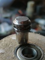
The old winch had a sort of a U-shaped bracket that held the bobbin, with bearings at either end. I did away with that in the interests of doing a really rough job, and so now have no outboard bearing. The driving cog is bolted to one of the end plates of the old bobbin, which mates with a sort of a pinion sun gear output from the planetary box. That pinion sun thing just pushes into the end of the box, then the end-plate pushes onto the pinion. It's not really a snug fit or anything, just kind of floppy. So when the chain tension pulls on it, it just pops out!
Grah.
So I'm thinking some sort of overly-complicated cantilevered retaining device, arching over from the side of the gearbox housing, with a little pushy bit reaching over the chain to press down in the centre of the bobbin plate. I think I'll be able to locate a bearing on top of the plate so that when it turns the pushy bit won't cause too much drag. Actually the pushy bit doesnt have to do much axial pushing, just counter the radial force from teh chain tension. So hopefully that'll be loading the bearing appropriately.
Does that sound like a good enough idea to suit the kind of Mickey Duck approach I've been following so far? I have to admit I do have concerns that its mechanical implementation is somewhat out of my skill level, but we'll see.
BTW if I get this sorted, someone with a video camera said they'd include me in their documentary they're making for the television!
Eric
edited to reinstate images