The FIRST home-built downtube frame-mounted 48v battery pack

nukezero

10 kW
Joined
Jul 2, 2013
Messages
560
Location
Los Angeles, CA
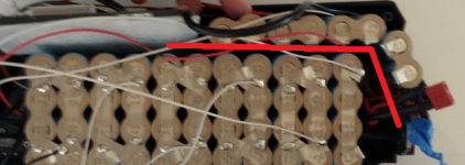
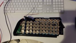
YES! Finally, I have built my FIRST ever battery pack to my liking and specifications. Wow, it was not for the faint of heart. Couple of sparks and gotchas! Solder wire touched the battery tops. No big smoke and nothing major, thank the earth.

Quickly want to mention that if you don't have any knowledge with electronics, I highly suggest you just buy a pack from lectric-cycles or em3ev! Highly, Highly! I had a few gotcha moments here and there by accident. You don't want to hook these things up on purpose and get a big poof of smoke and sparks.

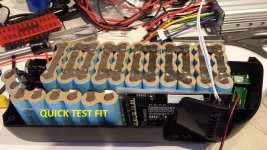
I started on this project to build a hi-discharge, light-weight, cheap, SAFE, and easy-to-manage battery pack. I wanted the frame-mounted downtube packs because it's low maintenance and 10Ah is really all I need.

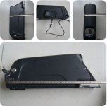
1. Several concerns about this battery case are:
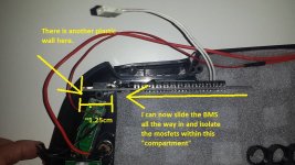
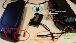
-It requires a special BMS to use the power switch function and USB port. That is true unless you can figure out a way to route the power switch wire out of the box somehow and use that as a ignition+ to a Infineon controller. There are no other "exits" available other than the +/- terminals. You COULD punch a whole.. but yea.

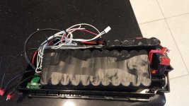
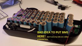
-They said No full size BMS can fit. Well, I'm here to PROVE THAT WRONG! I stuck a full size BMS in there (48v 13s Signalabs) I think this is the same BMS as pingbattery.

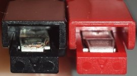
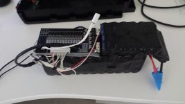
2. Special-thanks to voicecoil for opening up his em3ev pack because I got to see how it worked. One was to use deans plug at the discharge ports. This is useful because when you want to remove the entire pack.

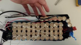
3. *edit* After 50 cycles, I confirm everything is running well and decided to open up for inspection, and now hot-glued the cells together. In addition, I've heat-shrink wrapped it as well using quality wraps from batteryspace.com.


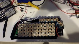
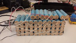
I decided to buy Samsung 18650-25R 2.5Ah cells from eBay. This is what ebikebirt and miguellart and everybody else did. The batteries arrived WITHIN A WEEK!!! Holy batman, that was SUPER fast. I paid less than $6.40/cell USD plus $88 dollar Fedex international shipping. It took 5 days. The vendor helped me tab-weld all the batteries including 1S4P and 2S1P. It's best to buy some spares too like I did.

So... now, I have the ONLY pack with the best cells that no vendor is offering yet (supposedly em3ev will be offering this in May) for a fraction of the cost.


Specs:

Samsung 18650-25R 2500mAH 48V
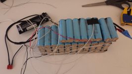
13S/4P = 48V nominal, 54.6V maximum
1 cell = 20Amp max discharge = 8C

Okay, enough said, here are all the pictures. ENJOY :D
 

Attachments

  • battery main.JPG
    battery main.JPG
    44.5 KB · Views: 6,413
  • 10.jpg
    10.jpg
    77.7 KB · Views: 6,412
  • 8.jpg
    8.jpg
    53.4 KB · Views: 6,412
  • 6.jpg
    6.jpg
    85.4 KB · Views: 6,412
  • 5.jpg
    5.jpg
    74.5 KB · Views: 6,412
  • 4.jpg
    4.jpg
    64.9 KB · Views: 6,412
  • 3.jpg
    3.jpg
    86.3 KB · Views: 6,411
  • 2.jpg
    2.jpg
    62.4 KB · Views: 6,412
  • 1.jpg
    1.jpg
    87.9 KB · Views: 6,414
  • 0.jpg
    0.jpg
    65 KB · Views: 6,413
  • 13.jpg
    13.jpg
    78.2 KB · Views: 6,413
  • 11.jpg
    11.jpg
    75.3 KB · Views: 6,413
  • wiring.jpg
    wiring.jpg
    67 KB · Views: 5,898
Nicely done. You got the cells you wanted. Very nice you were able to get them tab welded in parallel groups.
 
thanks for posting this. I built my second this week, same cells. I wonder if i shall keep more distance between cells with different potential :? I have no idea what voltage the heat shrink of these cells was made for.. I see you have some cells located cross the "main" pack in the middle. So you may have ~40V in between 2 cells? But i see you have add some extra distance there..is that necessary for isolation?
 

Attachments

  • Untitled.png
    Untitled.png
    84.7 KB · Views: 6,323
crossbreak said:
thanks for posting this. I built my second this week, same cells. I wonder if i shall keep more distance between cells with different potential :? I have no idea what voltage the heat shrink of these cells was made for.. I see you have some cells located cross the "main" pack in the middle. So you may have ~40V in between 2 cells? But i see you have add some extra distance there..is that necessary for isolation?

+1

Fire spotted :!:

You need to prevent cells to cells chaffing as well as balance wire chaffing. Bike is a high vibration environment...

ps: shrink wrap will wear over time due to chaffing... and fire will happen..
 
you don't have to use the nickel strap for the serial connections. you can use regular 12AWG solid wire from one 4P section to the next.

and then you can solder the serial connecting wires to the paralleling nickel strap between the cells, not on top of the cell. use two wires for 100-200A, soldered between the ultimate and penultimate cell on each parallel group.

i use that polyethylene foam felt a lot too. but if you have larger shunt currents the BMS will get so hot it melts the foam, and may do that on the charging mosfet which gets really hot on the ping signalab sometimes when the gate voltage hangs in the transition range.
 
crossbreak said:
thanks for posting this. I built my second this week, same cells. I wonder if i shall keep more distance between cells with different potential :? I have no idea what voltage the heat shrink of these cells was made for.. I see you have some cells located cross the "main" pack in the middle. So you may have ~40V in between 2 cells? But i see you have add some extra distance there..is that necessary for isolation?

Yes, I have 11 packs of 4P that goes across creating ~40V. Then I use two 14awg wires that run out from the last 4p tabs to the top. The top row cells are actually 2S1P which I then converted to 2S4P. That gives me 7.2V/10mAH. 7.2V + 40V = 47.2V.

cwah said:
crossbreak said:
thanks for posting this. I built my second this week, same cells. I wonder if i shall keep more distance between cells with different potential :? I have no idea what voltage the heat shrink of these cells was made for.. I see you have some cells located cross the "main" pack in the middle. So you may have ~40V in between 2 cells? But i see you have add some extra distance there..is that necessary for isolation?

+1

Fire spotted :!:

You need to prevent cells to cells chaffing as well as balance wire chaffing. Bike is a high vibration environment...

ps: shrink wrap will wear over time due to chaffing... and fire will happen..

how about my setup? Are there any fire risk that you see?

dnmun said:
you don't have to use the nickel strap for the serial connections. you can use regular 12AWG solid wire from one 4P section to the next.

and then you can solder the serial connecting wires to the paralleling nickel strap between the cells, not on top of the cell. use two wires for 100-200A, soldered between the ultimate and penultimate cell on each parallel group.

i use that polyethylene foam felt a lot too. but if you have larger shunt currents the BMS will get so hot it melts the foam, and may do that on the charging mosfet which gets really hot on the ping signalab sometimes when the gate voltage hangs in the transition range.

That's what I did was to run the 2 14awg wires to the last 2S4P pack at the top. There was no other way to do this. The entire pack sits in the case tightly but not like overly jammed in. There is no room for much movement or rubbing. The points where the battery makes contact with plastic, I put foam or put 5 layers of electrical tape. After a couple rides, I will open up this pack and check for physical wear from any movement in the case that I did not foresee.


My main concern now is the BMS. The 5 mosfets are close to a cell which sits horizontally. I'm not sure if these mosfets will get hot during charging, discharging, or balancing? I have no shunt modifications or any other modifications. I will only be charging this pack up using 2Amps, which would likely take me 3-4 hours to charge up. Anyone care to chime in on whether or not these mosfets will burn hot during any operation?
 
999zip999 said:
How well balance were the parelle cell groups before assemely ?

All cells were at 3.64V. No large variation.

I will be doing that this week. My 48v charger I bought is dead. I will be buying another one in the store and then opening it up to modify out the connector to DC plug.

The ONLY concern still which is bugging me is that the mosfets are close to one of the cells. However, I believe this is a Ping v2.5 BMS and was supposedly told they don't run hot like V1s. plus I'll be charging at 2A anyway. I limited my Infineon controller to 25A max. This BMS supposed to handle 30A.
 
file.php


Have you considered hacking off the unused 14,15,16 empty end.
rewire the temp switch to unused pins on 17 way connector and link it up to where they need to go.

This will keep the FETs from jamming under/in between the cells.

How does the shunt on the BMS cut off drive to the FETs?
Can't see opamps or similar circuits. Anything on other side?

I would suggest cardboard sheet or some kind of extra protection than just the light blue cell socks.
You see most industrial drills etc with cardboard tubes. For good reason. Chaffing.

Would be great if the usb charge port allowed for cell data logfile transfer to USB stick.

Have you done load test and charge test before you close it uLooks like a tidy module for your bike.
7c
 
cwah said:
Fire spotted :!:

so what do you propose as cell separator. I dont like the square separators. I'd like triangular ones, like Bosch uses
from http://www.pedelecforum.de/forum/index.php?threads/infos-%C3%BCber-bosch-antrieb-can-bus-daten-usw.17799/
attachment.php


from http://www.e-bikeshop.co.uk/blog/post/e-bikeshop-visit-bosch-for-training-session-on-the-new-2014-ebike-system/
Inside-Bosch-PowerPack-Battery-400-300.jpg


Any idea where i could buy them? Or can i simply use an old tire tube as isolator?
 
7circle said:
file.php


Have you considered hacking off the unused 14,15,16 empty end.
rewire the temp switch to unused pins on 17 way connector and link it up to where they need to go.

This will keep the FETs from jamming under/in between the cells.

How does the shunt on the BMS cut off drive to the FETs?
Can't see opamps or similar circuits. Anything on other side?

I would suggest cardboard sheet or some kind of extra protection than just the light blue cell socks.
You see most industrial drills etc with cardboard tubes. For good reason. Chaffing.

Would be great if the usb charge port allowed for cell data logfile transfer to USB stick.

Have you done load test and charge test before you close it uLooks like a tidy module for your bike.
7c

Wait a minute... are you seriously asking me to SAW off the board so i can reduce the physical size of the PCB? Hrrm,, never thought about that and it would certainly help. Yes, there is a small problem where the mosfets are sort of somewhat jammed underneath one of the cells. That's why I was asking how hot it would get. But now that you gave me this idea of sawing off the board, it would Certainly give me more than enough clearance....

I don't care for the temp sensor, but yes if I saw it off, there will be open traces at the end , no? i haven't put a load test on it... actualy, i don't have any load test equipment.

Now, I'm not sure why you need to short the 3 pins for 14,15,16 empty cell sense wires on the optoelectronics?? What's the point of doing this? There are no circuittry there.
 
Does anyone know what is the easiest way I can hook up this 48v pack and sort of drain it at 1 or 2Ah ? I know someone mentioned a standard 60w lightbulb.. but then I would have to solder two wires coming out of it right?

What's a safer way? Is there anything I can buy at homedepot and just use that?
 
Guys, I'm thinking somewhere down the line, I will need to use a switch or some kind of precharge circuit. Look at what happened to my negative terminal on the AndersonPP connector? This is after about 5 connect/disconnects and I hear a tiny "spark" noise each time I connect it. The positive terminal has no problem. Electrons flow out of the negative terminal as I learned in physics. Looks like this battery pack has a PUNCH!

My girlfriend's 36V 10ah 18650 Samsung 26F doesn't do this and also uses AndersonPP's. It also doesn't make the spark noise.

I wonder how many connect/disconnect this terminal will last. Does anyone have any experience in how long this will last and whether or not it is a big issue down the road?
 

Attachments

  • terminal.jpg
    terminal.jpg
    40.4 KB · Views: 6,163
The pp's should last quite awhile. Their design is to take the spark at the tip, then when fully inserted all contact is on the still clean blade inside. So the tip can be very trashed, and still work fine.

But nothing wrong with a precharge circuit too.

I see now what you mean about the cell too close to the fets. Partially on top of them. That will be a problem. That topside of the fets can be hot enough to burn away heat shrink.

I wonder if you could possibly relocate the fets on the board. Like put them on a daughter board? The bms can't be flipped, so the fets point to the other end of the box?
 
nukezero said:
Guys, I'm thinking somewhere down the line, I will need to use a switch or some kind of precharge circuit. Look at what happened to my negative terminal on the AndersonPP connector? This is after about 5 connect/disconnects and I hear a tiny "spark" noise each time I connect it. The positive terminal has no problem. Electrons flow out of the negative terminal as I learned in physics. Looks like this battery pack has a PUNCH!

My girlfriend's 36V 10ah 18650 Samsung 26F doesn't do this and also uses AndersonPP's. It also doesn't make the spark noise.

I wonder how many connect/disconnect this terminal will last. Does anyone have any experience in how long this will last and whether or not it is a big issue down the road?

The search facility here is good - There are threads about making an anti-spark connector. Try pre-charge too.
 
you cannot just cut off the end because the circuit current that runs through the opto transistors runs in those two little traces along that top edge over to the thermal breaker and then back to the collector of the first opto on channel 16.
 
dogman said:
The pp's should last quite awhile. Their design is to take the spark at the tip, then when fully inserted all contact is on the still clean blade inside. So the tip can be very trashed, and still work fine.

But nothing wrong with a precharge circuit too.

I see now what you mean about the cell too close to the fets. Partially on top of them. That will be a problem. That topside of the fets can be hot enough to burn away heat shrink.

I wonder if you could possibly relocate the fets on the board. Like put them on a daughter board? The bms can't be flipped, so the fets point to the other end of the box?

Last night it occurred to me that there is yet ANOTHER way to get MORE room out of this box! When something is in your way, what do you do? CUT THAT WALL DOWN! Actually, as it turns out, there is no structural rigidity problem when I cut this wall on both sides of the cases. It serves only to somewhat brace the screw base. I don't see that it is a load bearing column or ending. Nothing pushes against it or pulls it down. It serves to just guide the screw from one end to the other and keep the screw straight. The BMS is not heavy at all. I put quite a bit amount of finger force to bend that post up and down and it held fairly well. (2-3-lbs)

Anybody who has concerns about this, we can probably just put a thin layer of JB-WELD on the lower wall to the post to stiffen it up :D but I really don't see a need for it at all.

Anyhow, I had the ingenious idea to cut this wall and now I can slide the BMS all the way in. Then I thought, I'm going to reverse the BMS so that the mosfets will stay in that little compartment. What do you guys think? I killed 2 birds with one stone!
 

Attachments

  • D3.jpg
    D3.jpg
    86 KB · Views: 6,108
As long as the shell doesn't do any unwanted flexing, you're fine. It looks good like that IMO.

Thanks for all the photos, I have a box in the mail and will be doing this soon. BTW, we should meet up, I'd love to check out your rides.
 
This is PRECISELY WhY I build my own packs. I can't trust anybody else to do this. Specially if a BMS is involved.

BMS-free since the beginning :D

KUDOS on making the pack from 25R's I'm pretty sure that looking back at all these pictures reassures that you've done it right.
 
yep i learn a lot here, too.

yep the 25R is nice. I may think too much about sinking heat...did a ride with a test pack today that did not really get warm with 40A peak with 4p :? Even in the packpack where it is "well isolated" from being cooled

any resistance figure yet?

Best thing of the 25R: It is a lot cheaper than the VCT5 :D But does as well

here: http://www.dampfakkus.de/akkuvergleich.php?akku1=154&akku2=490&akku3=485&akku4=523&akku5=507&akku6=&a=5
file.php
 

Attachments

  • cell_benchmark_5A.png
    cell_benchmark_5A.png
    49.1 KB · Views: 3,115
cal3thousand said:
As long as the shell doesn't do any unwanted flexing, you're fine. It looks good like that IMO.

Thanks for all the photos, I have a box in the mail and will be doing this soon. BTW, we should meet up, I'd love to check out your rides.

We sure should. My girlfriend has the bafang 36v mid-drive on her townie. I"m building a mid-drive with LightningRod's mid-drive.
 
crossbreak said:
yep i learn a lot here, too.

yep the 25R is nice. I may think too much about sinking heat...did a ride with a test pack today that did not really get warm with 40A peak with 4p :? Even in the packpack where it is "well isolated" from being cooled

any resistance figure yet?

Best thing of the 25R: It is a lot cheaper than the VCT5 :D But does as well

here: http://www.dampfakkus.de/akkuvergleich.php?akku1=154&akku2=490&akku3=485&akku4=523&akku5=507&akku6=&a=5
file.php

I really wanted to get the VTC5's. But they were too expensive. But yeah, the 25R has simliar performance for like 30% cheaper. Anyhow, I'm fairly happy. These are one of the best high powered cells you can get from Samsung that's atleast 2500mAH. I'll upgrade again when Samsung comes out with a 3000mAH 30R.
 
also, since you will not be using the thermal breaker on your BMS, you can cut it out and install a small switch there to turn the battery on and off. then you don't need to use a separate switch for precharge and you don't have to leave the battery active when you leave the bike so it cannot be stolen if you hide the switch.
 
dnmun said:
also, since you will not be using the thermal breaker on your BMS, you can cut it out and install a small switch there to turn the battery on and off. then you don't need to use a separate switch for precharge and you don't have to leave the battery active when you leave the bike so it cannot be stolen if you hide the switch.

by replacing the breaker with a switch, do you think it will works as on/off switch ? i think this is worth trying, and if it works. problems solved :wink:
 
Back
Top