
Canonical source: http://syonyk.blogspot.com/2016/01/trek-valencia-ride-bionx-battery-pack_9.html
Trek Valencia Ride+ BionX Battery Pack Teardown: Part 1
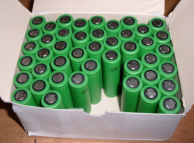
It's been a while since I've torn down a battery pack! The last one I tore down was a BionX 9.6AH 36v pack, back in June. I've been busy since then, and have rebuilt a few packs, but I haven't played with anything new.
Until now!
I've got a Trek Valencia Ride+ (powered by BionX) battery pack to rebuild if possible. The first part in rebuilding a battery pack is, of course, to tear it down and figure out what I'm dealing with.
The Trek Valencia+ (or Trek Valencia Ride+) is a Trek bike with a factory installed BionX kit. The battery is a 6.4Ah 40v battery (which is a bit unusual as far as voltage goes), for a total nominal capacity of 260Wh. It's a fairly small battery by ebike standards, but it's also fairly light, and the BionX kits are quite efficient (being pedal assist and having regen). This bike was mostly notable for the rear spokes being utterly incapable of handling the weight and furious power of the BionX motor, and spending more time in the shop having spokes replaced than actually being on the road.
Previous research indicates that it's a 11S4P cell arrangement of some form, and that it's a bit tricky to get apart.
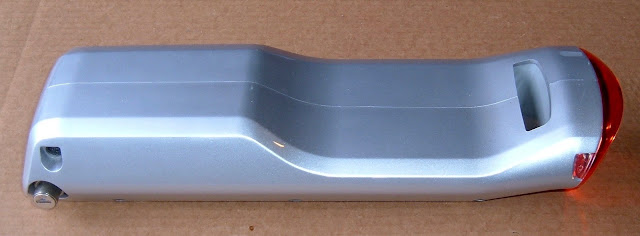
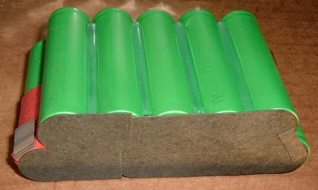
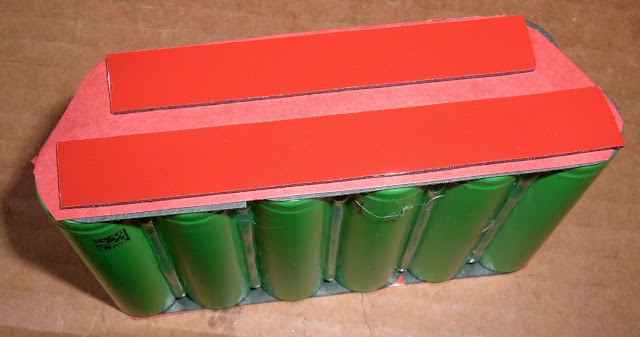
The pack looks like this:
If you're interested in a bunch of teardown photos and some analysis (of course you are), read on!
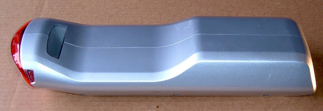
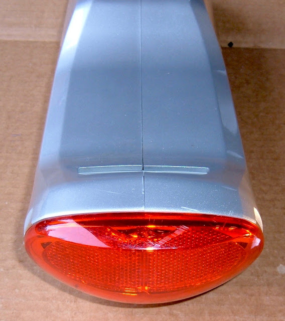
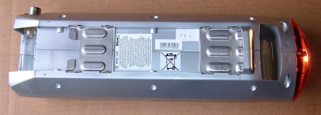
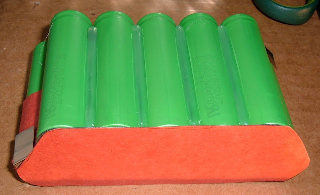
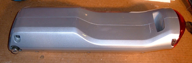
Pack Exterior
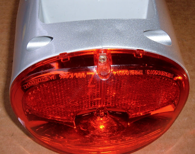
The pack is a pretty slick piece of plastic. It's not particularly heavy, it's well engineered, it's got a metal lock, and it has an integrated tail light! I really like the tail light - electric bikes without pack-powered lighting drives me nuts.
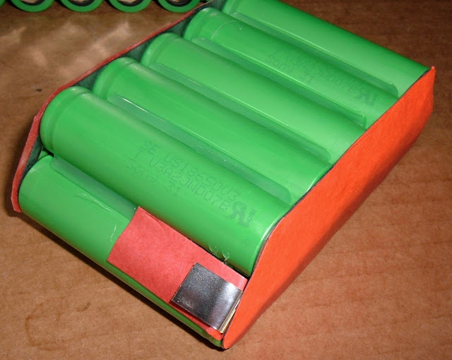
The underside of the pack shows the twin metal mounting brackets, and on the left you can see the lock. The lock is metal, well buried in the plastic, and should keep the pack installed unless the owner chooses to remove it. Very nice! I'm a fan of the BionX pack locks - they do a great job of keeping the pack on the bike.
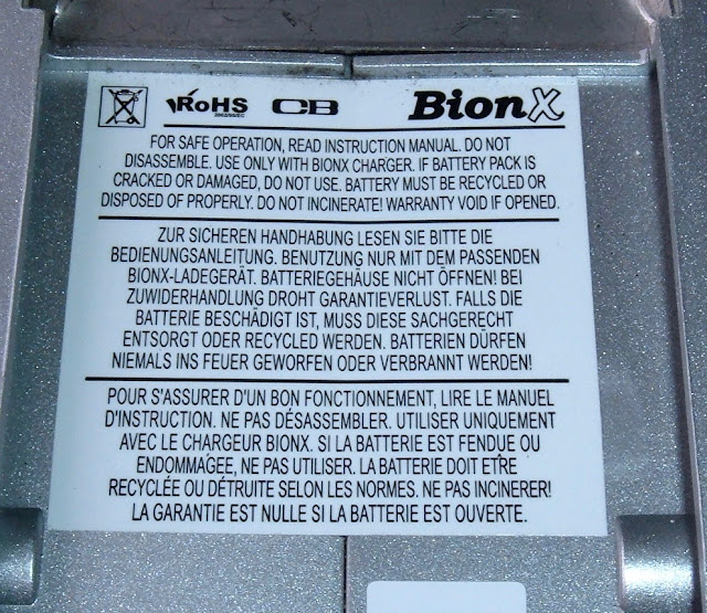
Then, of course, I come to this part. It's always there.
The warnings. Do not disassemble. Warranty void if opened. Something something don't do what you're about to do, and if you do, we're not at fault. However, it's a label, not a cop. Sadly for the label, I'm about to disassemble and open this pack. I'd prefer something about "qualified personnel" or something. It really doesn't matter, though - the old battery packs are so far out of warranty that it just doesn't matter anymore.
Yes, I void warranties. Or, more preferably, work on things that have no warranty remaining. If it's broken, you're not going to make it any worse. At the absolute worst, you still have something broken, and you've learned something.
The Fasteners
It's time to start diving into the pack. A bit of research indicates it's a pain in the ass. Well, I still need to get it open if I want to rebuild it, so in I go!
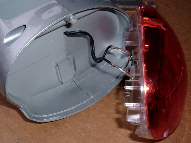
The tail light is held on by a single Phillips head screw. No problems here!
The rest of the bolts are BionX-standard hex heads. Out they come! On the previous packs I've rebuilt, the pack then comes apart easily.
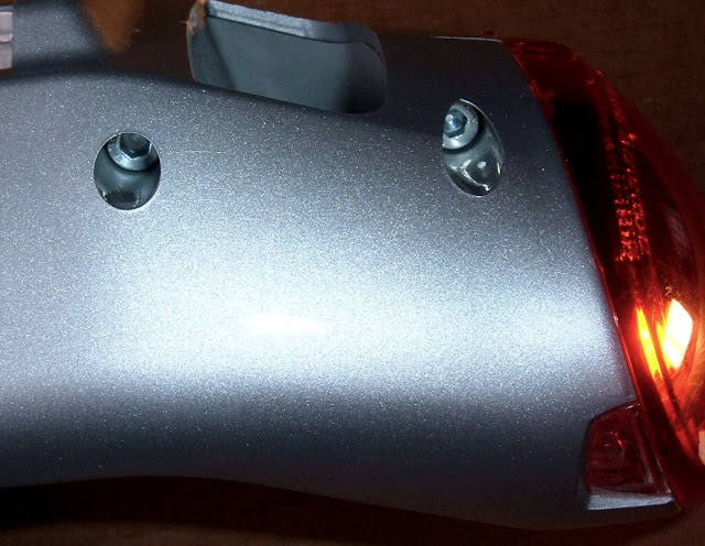
I was hopeful that after the tail light coming free, there'd be something useful. Perhaps a battery that slid out?
Nope. Just a clip.
The First Side
Being forewarned that some serious prying was in the works, I started prying away. Using the mounting brackets to apply pressure to the pack helped, as did a few standard screwdrivers.
It took quite a while to get the first major crack opening up. This is not an easy pack to tear down. It's brutal on fingers, and it takes a serious amount of brute force to get it free. I'm not happy with this.
Finally, though, I got it started.
The procedure from this point involved a lot of brute force, and a non-trivial amount of heat (from my kerosene garage heater). The pack is sharp, awkward, and not at all fun to open. It seriously don't want to be opened.
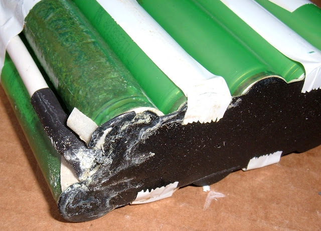
Once it's open, the reason it's so hard to get open is very, very obvious. Giant blobs of some sort of foamy adhesive. The battery wasn't going anywhere.
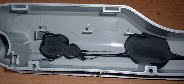
Just two? Nope! Three huge blobs of whatever this stuff is. Seriously. Why? Some foam padding would have done the same job without making the pack a nightmare to open.
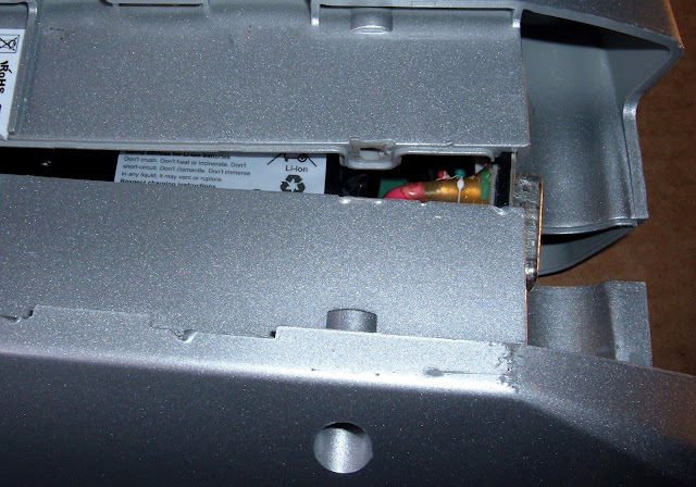
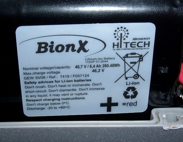
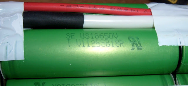
In any case, it's open, and the internal battery label is visible.
Helpfully, it tells me it's an 11S4P battery - I don't think I've ever seen this on a label before.
Doing some maths, 40.7/11 = 3.7, and 6.4/4 = 1.6 - so, as I suspected, it's using 1600mAh standard cells. It's probably the same Sony US18650V cells that the other BionX packs of this era use - which is good news, because that means I can put in 2200mAh US18650V3 replacements when I rebuild, for a total pack capacity of 8.8Ah - 37% more capacity in the same space!
Port and Sealant
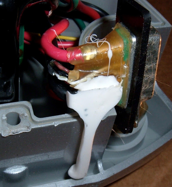
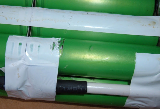
I think BionX got a by-the-barrel discount on "sticky stuff" when they built this pack. There's a bunch of it around the connector (the yellow stuff), and more white stuff securing the yellow glop into the pack.
I don't mind the yellow strain relief. It looks like waterproofing, which is cool. It turns out, people do ride bikes in the rain. Even electric bikes.
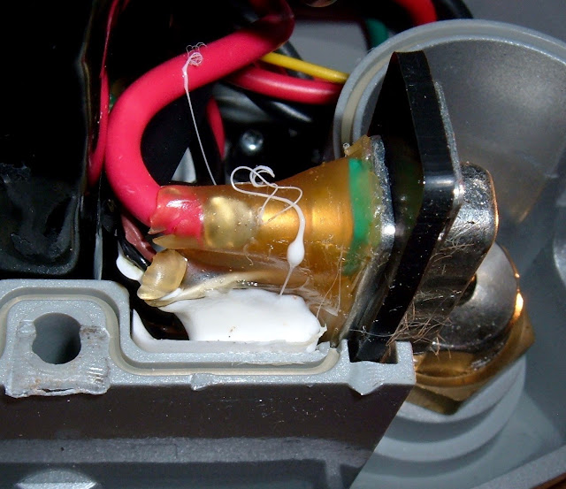
Unfortunately, the white glop didn't stick. It literally came right out. I don't know why it was there. Someone put a lot in, though.
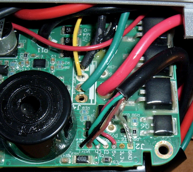
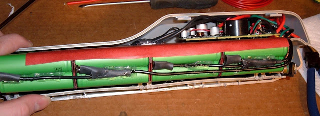
Controller
The controller is crammed up in the bulge of the pack. The thermal fuse is visible to the left - this is a fuse that breaks the negative line if the pack gets too hot. It's a nice safety feature, as it will interrupt both charging and discharging. I don't know if it will reset when things cool down or if it is a one time fuse. If I'm finding out, I'm having a really bad day.
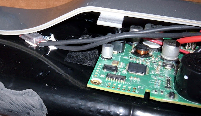
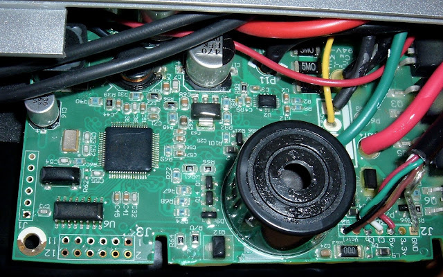
The controller is a pretty standard looking BionX controller, with the beeper that is used for power on/off notifications and the occasional "Please charge me..." notification if the pack is dying a slow death in the garage.
Interestingly, this controller has some sort of conformal coating on it. The whole board is covered in it. What this means is that the controller is likely to be incredibly water resistant, or even waterproof (I'm not going to test it). This is great - electric bikes can and do get wet, and the older downtube packs don't have this coating. I don't know if BionX or Trek decided on it, but I'm really glad to see it.
Getting the Battery Out
Trek? BionX? I hate both of you right now.
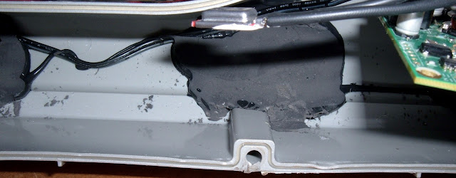
The pain of getting the outer shell apart is nothing compared to the pain and toil involved in getting the battery out. The other side is using the exact same adhesive, and I have a lot less to grab or pry from. The force involved is enough to do serious damage to the case, even being careful. It's simply not designed to come out.
After about half an hour, roasting the case on top of a kerosene heater to warm it up, pulling out as much gunk as I could, an awful lot of prying, and some bent plastic, the pack came out.
Let me be clear: This is absurd. There's no good reason to secure your pack like this. Some foam padding would have done exactly the same job without making it a genuine nightmare to rebuild.
In any case, it finally came out in one piece.
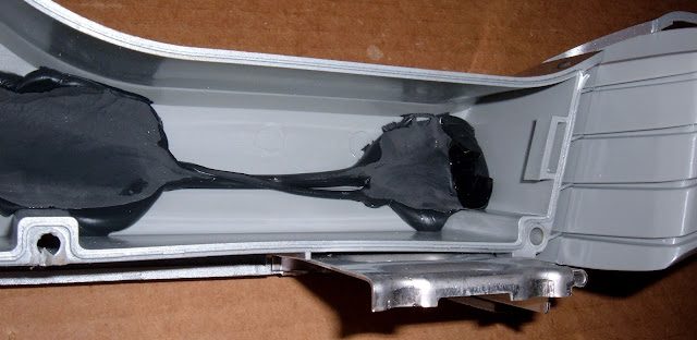
More of that damned black goo.
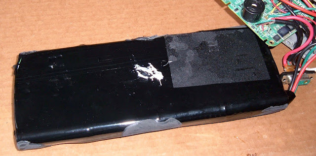
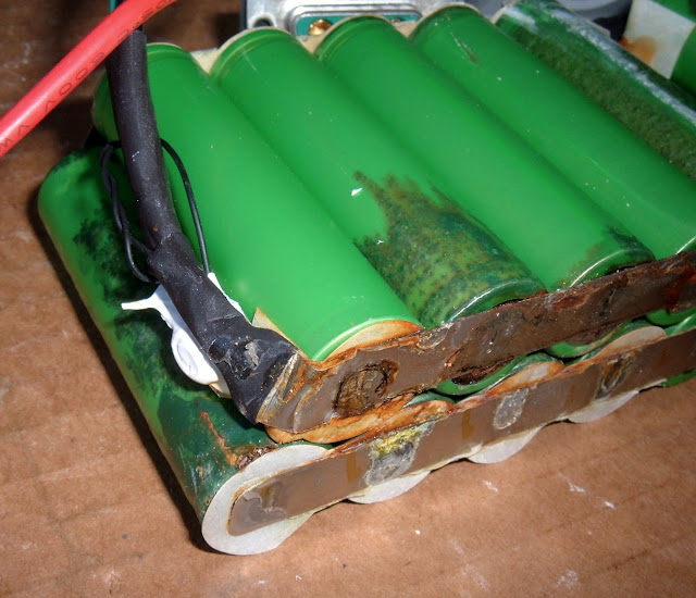
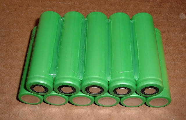
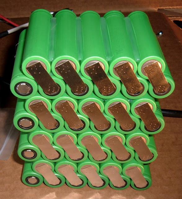
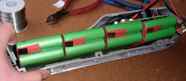
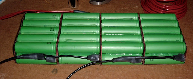
Battery Pack
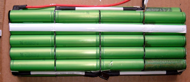
Finally. What I came for. The battery pack.
It's... actually sort of weird. I'm not sure what to make of it.
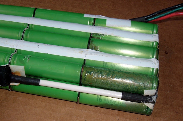
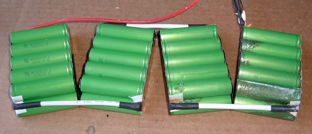
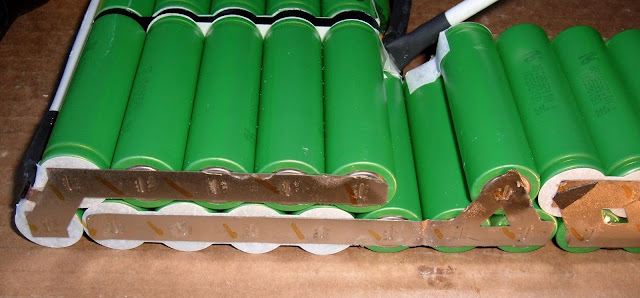
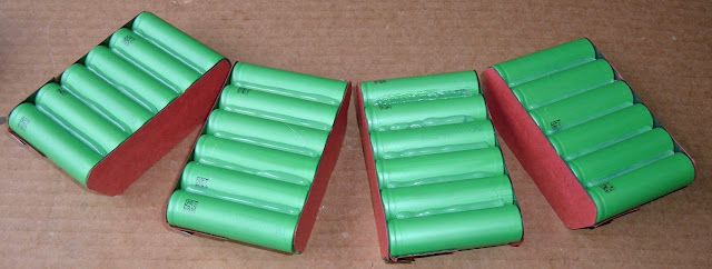
The bottom layer is 6 cells wide, and the top is 5. That makes 11 cell groups, and there are 4 of those. So it's definitely 44 cells, and somehow wired into the 11S4P arrangement promised on the label. I should point out that 4 and 11 don't go evenly into each other.
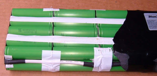
I can think of a few ways to do this, and none of them involve these weird bridge wires along the side. I think they're doing something really weird here... and it's probably going to be a nightmare to rebuild.

However, at least the cells are the Sony US18650V cells, as I suspected from the capacity. That's good news. About the last I'm going to get with this pack...
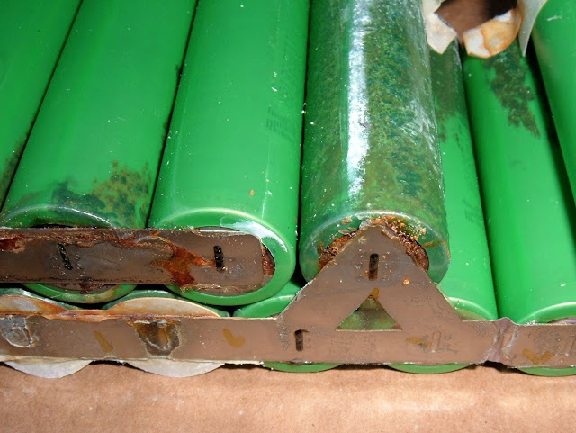
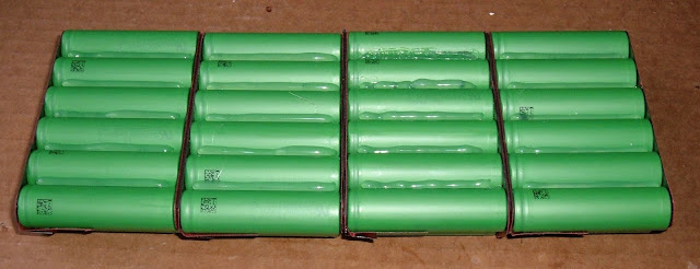
Cell Corrosion
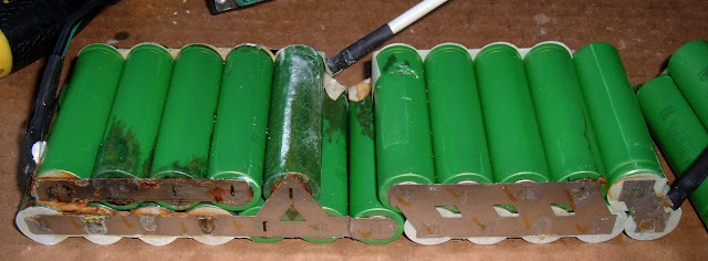
The rest of the wrapper is off, and... oh my. That's not good. I trust my readers, by now, realize that all the cells in the pack should look the same, and not be covered in that. At least it's inside the wrapper. Mostly.
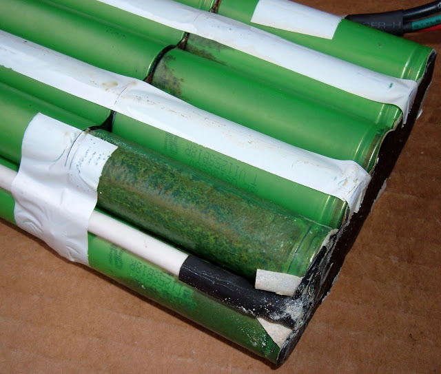
I'm not exactly sure what's happened here, but a bunch of the cells have some pretty nasty corrosion on them. I know I did a little bit of damage to the cells pulling them out, but I'm very confident I had nothing to do with this bit of horror.
I'm not sure if this is just surface corrosion on the case from water that got into the pack and pooled, if a cell vented at some point and this is corrosion from the vent gasses, or what.
I'll know more once I pull things further apart and can take a look at the individual cells.
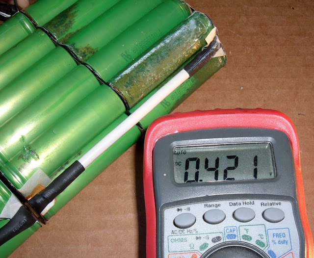
In any case, I've got a theory for why this pack isn't taking a charge...
This doesn't look like water damage to me, but... maybe? I don't have that much experience with vented cells long after they've vented, so this might be what happens. I have nothing to explain why they would vent, though.
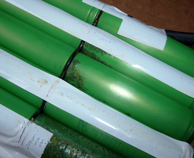
This damage, on the other hand, was me. I'm quite confident of that. That's the type of damage you get when prying a stubborn pack out of a huge cradle of glue. It doesn't appear to have done any real damage to the cell, just scraped the coating up a bit. I wouldn't put this back in a pack, but... oh, right. I'm rebuilding it with new cells!
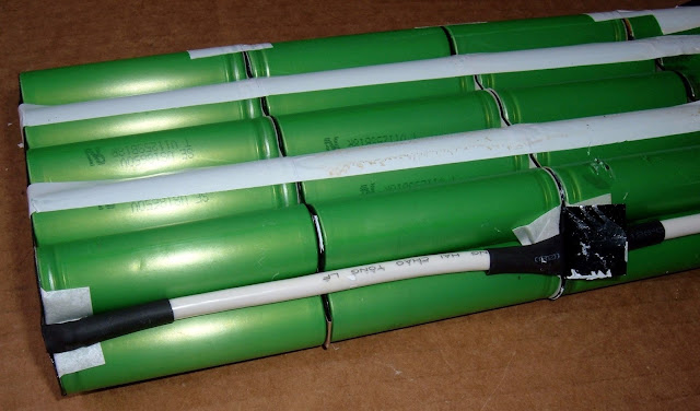
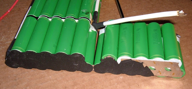
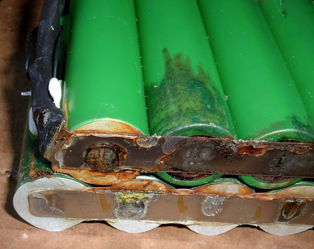
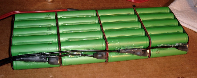
This is, by far, the ugliest pack I've pulled out. Ew. And the weird conductors along the side are going to take some work to figure out.
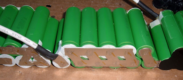
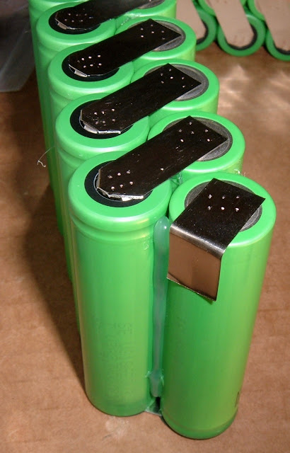
The other end of the pack looks OK. A few dents from getting it out.
I really, really hate applying a lot of force to battery packs, but that was literally the only way to get this thing free.
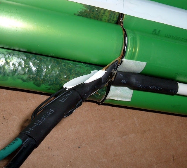
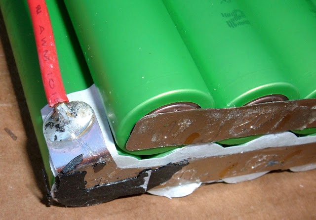
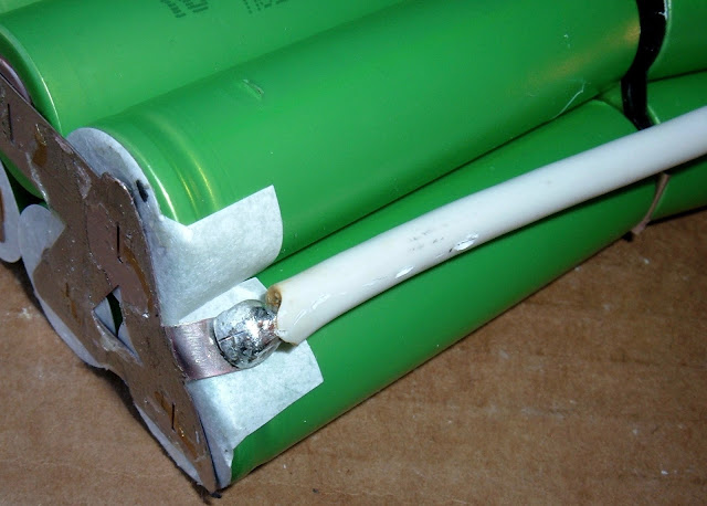
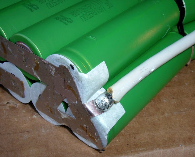
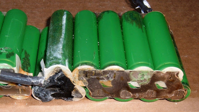
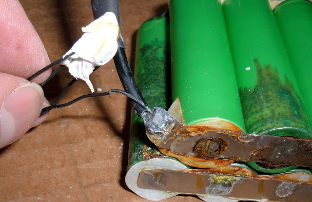
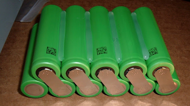
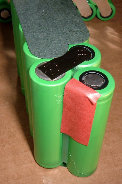
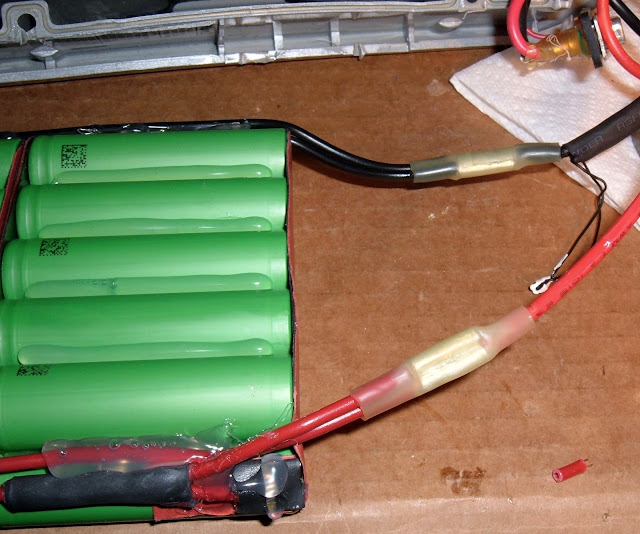
Here's the negative terminal. It's got what appears to be the thermal sensor attached, somehow. Hopefully through the green wire, since that's how BionX handles this on other packs. It comes in between a set of cells, but there's insulating material in between.
This pack arrangement does worry me a bit. If I'm right about how it's set up, there's a LOT of potential difference, kept apart by one tiny insulator. This might be why the pack is glued so firmly in place - to keep from shorting out. I can't say I'm a huge fan of this concept.
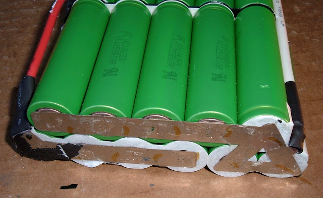
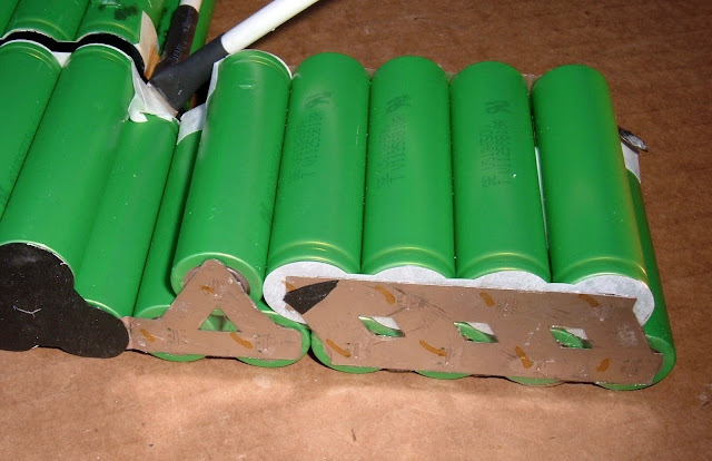
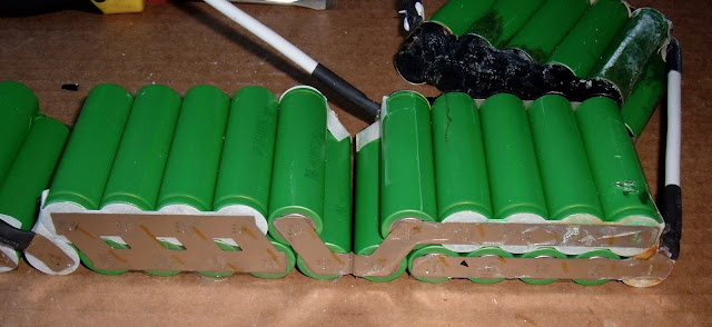
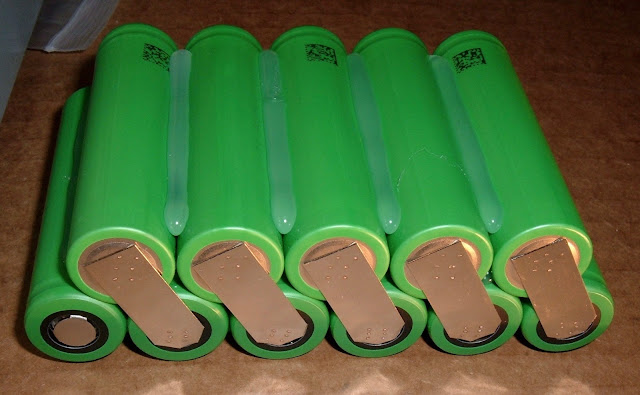
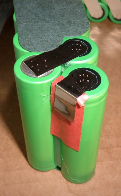
Alright. The top of the pack. Can I make any sense of this layout?
The positive terminal goes into the left side. Probably on the bottom. On the top, there is a set of 4 cells facing one way, with one facing the other way. At least on the three left-most regions. The rightmost region appears to have all the cells with the positive terminals facing right.
I've run through a bunch of different ideas on how this pack is laid out, and at this point, I honestly don't know what they've done.
I'm going to have to tear the pack down to find out, and I quite simply don't feel like tearing down a weird, corroded pack right now.
So, I'm going to go have a beer.
Trek Valencia Ride+ BionX Battery Pack Teardown: Part 1
It's been a while since I've torn down a battery pack! The last one I tore down was a BionX 9.6AH 36v pack, back in June. I've been busy since then, and have rebuilt a few packs, but I haven't played with anything new.
Until now!
I've got a Trek Valencia Ride+ (powered by BionX) battery pack to rebuild if possible. The first part in rebuilding a battery pack is, of course, to tear it down and figure out what I'm dealing with.
The Trek Valencia+ (or Trek Valencia Ride+) is a Trek bike with a factory installed BionX kit. The battery is a 6.4Ah 40v battery (which is a bit unusual as far as voltage goes), for a total nominal capacity of 260Wh. It's a fairly small battery by ebike standards, but it's also fairly light, and the BionX kits are quite efficient (being pedal assist and having regen). This bike was mostly notable for the rear spokes being utterly incapable of handling the weight and furious power of the BionX motor, and spending more time in the shop having spokes replaced than actually being on the road.
Previous research indicates that it's a 11S4P cell arrangement of some form, and that it's a bit tricky to get apart.
The pack looks like this:
If you're interested in a bunch of teardown photos and some analysis (of course you are), read on!
Pack Exterior
The pack is a pretty slick piece of plastic. It's not particularly heavy, it's well engineered, it's got a metal lock, and it has an integrated tail light! I really like the tail light - electric bikes without pack-powered lighting drives me nuts.
The underside of the pack shows the twin metal mounting brackets, and on the left you can see the lock. The lock is metal, well buried in the plastic, and should keep the pack installed unless the owner chooses to remove it. Very nice! I'm a fan of the BionX pack locks - they do a great job of keeping the pack on the bike.
Then, of course, I come to this part. It's always there.
The warnings. Do not disassemble. Warranty void if opened. Something something don't do what you're about to do, and if you do, we're not at fault. However, it's a label, not a cop. Sadly for the label, I'm about to disassemble and open this pack. I'd prefer something about "qualified personnel" or something. It really doesn't matter, though - the old battery packs are so far out of warranty that it just doesn't matter anymore.
Yes, I void warranties. Or, more preferably, work on things that have no warranty remaining. If it's broken, you're not going to make it any worse. At the absolute worst, you still have something broken, and you've learned something.
The Fasteners
It's time to start diving into the pack. A bit of research indicates it's a pain in the ass. Well, I still need to get it open if I want to rebuild it, so in I go!
The tail light is held on by a single Phillips head screw. No problems here!
The rest of the bolts are BionX-standard hex heads. Out they come! On the previous packs I've rebuilt, the pack then comes apart easily.
I was hopeful that after the tail light coming free, there'd be something useful. Perhaps a battery that slid out?
Nope. Just a clip.
The First Side
Being forewarned that some serious prying was in the works, I started prying away. Using the mounting brackets to apply pressure to the pack helped, as did a few standard screwdrivers.
It took quite a while to get the first major crack opening up. This is not an easy pack to tear down. It's brutal on fingers, and it takes a serious amount of brute force to get it free. I'm not happy with this.
Finally, though, I got it started.
The procedure from this point involved a lot of brute force, and a non-trivial amount of heat (from my kerosene garage heater). The pack is sharp, awkward, and not at all fun to open. It seriously don't want to be opened.
Once it's open, the reason it's so hard to get open is very, very obvious. Giant blobs of some sort of foamy adhesive. The battery wasn't going anywhere.
Just two? Nope! Three huge blobs of whatever this stuff is. Seriously. Why? Some foam padding would have done the same job without making the pack a nightmare to open.
In any case, it's open, and the internal battery label is visible.
Helpfully, it tells me it's an 11S4P battery - I don't think I've ever seen this on a label before.
Doing some maths, 40.7/11 = 3.7, and 6.4/4 = 1.6 - so, as I suspected, it's using 1600mAh standard cells. It's probably the same Sony US18650V cells that the other BionX packs of this era use - which is good news, because that means I can put in 2200mAh US18650V3 replacements when I rebuild, for a total pack capacity of 8.8Ah - 37% more capacity in the same space!
Port and Sealant
I think BionX got a by-the-barrel discount on "sticky stuff" when they built this pack. There's a bunch of it around the connector (the yellow stuff), and more white stuff securing the yellow glop into the pack.
I don't mind the yellow strain relief. It looks like waterproofing, which is cool. It turns out, people do ride bikes in the rain. Even electric bikes.
Unfortunately, the white glop didn't stick. It literally came right out. I don't know why it was there. Someone put a lot in, though.
Controller
The controller is crammed up in the bulge of the pack. The thermal fuse is visible to the left - this is a fuse that breaks the negative line if the pack gets too hot. It's a nice safety feature, as it will interrupt both charging and discharging. I don't know if it will reset when things cool down or if it is a one time fuse. If I'm finding out, I'm having a really bad day.
The controller is a pretty standard looking BionX controller, with the beeper that is used for power on/off notifications and the occasional "Please charge me..." notification if the pack is dying a slow death in the garage.
Interestingly, this controller has some sort of conformal coating on it. The whole board is covered in it. What this means is that the controller is likely to be incredibly water resistant, or even waterproof (I'm not going to test it). This is great - electric bikes can and do get wet, and the older downtube packs don't have this coating. I don't know if BionX or Trek decided on it, but I'm really glad to see it.
Getting the Battery Out
Trek? BionX? I hate both of you right now.
The pain of getting the outer shell apart is nothing compared to the pain and toil involved in getting the battery out. The other side is using the exact same adhesive, and I have a lot less to grab or pry from. The force involved is enough to do serious damage to the case, even being careful. It's simply not designed to come out.
After about half an hour, roasting the case on top of a kerosene heater to warm it up, pulling out as much gunk as I could, an awful lot of prying, and some bent plastic, the pack came out.
Let me be clear: This is absurd. There's no good reason to secure your pack like this. Some foam padding would have done exactly the same job without making it a genuine nightmare to rebuild.
In any case, it finally came out in one piece.
More of that damned black goo.
Battery Pack
Finally. What I came for. The battery pack.
It's... actually sort of weird. I'm not sure what to make of it.
The bottom layer is 6 cells wide, and the top is 5. That makes 11 cell groups, and there are 4 of those. So it's definitely 44 cells, and somehow wired into the 11S4P arrangement promised on the label. I should point out that 4 and 11 don't go evenly into each other.
I can think of a few ways to do this, and none of them involve these weird bridge wires along the side. I think they're doing something really weird here... and it's probably going to be a nightmare to rebuild.
However, at least the cells are the Sony US18650V cells, as I suspected from the capacity. That's good news. About the last I'm going to get with this pack...
Cell Corrosion
The rest of the wrapper is off, and... oh my. That's not good. I trust my readers, by now, realize that all the cells in the pack should look the same, and not be covered in that. At least it's inside the wrapper. Mostly.
I'm not exactly sure what's happened here, but a bunch of the cells have some pretty nasty corrosion on them. I know I did a little bit of damage to the cells pulling them out, but I'm very confident I had nothing to do with this bit of horror.
I'm not sure if this is just surface corrosion on the case from water that got into the pack and pooled, if a cell vented at some point and this is corrosion from the vent gasses, or what.
I'll know more once I pull things further apart and can take a look at the individual cells.
In any case, I've got a theory for why this pack isn't taking a charge...
This doesn't look like water damage to me, but... maybe? I don't have that much experience with vented cells long after they've vented, so this might be what happens. I have nothing to explain why they would vent, though.
This damage, on the other hand, was me. I'm quite confident of that. That's the type of damage you get when prying a stubborn pack out of a huge cradle of glue. It doesn't appear to have done any real damage to the cell, just scraped the coating up a bit. I wouldn't put this back in a pack, but... oh, right. I'm rebuilding it with new cells!
This is, by far, the ugliest pack I've pulled out. Ew. And the weird conductors along the side are going to take some work to figure out.
The other end of the pack looks OK. A few dents from getting it out.
I really, really hate applying a lot of force to battery packs, but that was literally the only way to get this thing free.
Here's the negative terminal. It's got what appears to be the thermal sensor attached, somehow. Hopefully through the green wire, since that's how BionX handles this on other packs. It comes in between a set of cells, but there's insulating material in between.
This pack arrangement does worry me a bit. If I'm right about how it's set up, there's a LOT of potential difference, kept apart by one tiny insulator. This might be why the pack is glued so firmly in place - to keep from shorting out. I can't say I'm a huge fan of this concept.
Alright. The top of the pack. Can I make any sense of this layout?
The positive terminal goes into the left side. Probably on the bottom. On the top, there is a set of 4 cells facing one way, with one facing the other way. At least on the three left-most regions. The rightmost region appears to have all the cells with the positive terminals facing right.
I've run through a bunch of different ideas on how this pack is laid out, and at this point, I honestly don't know what they've done.
I'm going to have to tear the pack down to find out, and I quite simply don't feel like tearing down a weird, corroded pack right now.
So, I'm going to go have a beer.


") Otherwise it would have taken me a long while as well. I just didn't copy the hyperlinks over when I copied the post to ES. I quite appreciated it, though it still took me close to an hour of hard work to get the thing apart. And your post provided me enough information to know I stood a good chance of rebuilding this thing (that it was a BionX system similar to what I knew with the older ones).
Otherwise it would have taken me a long while as well. I just didn't copy the hyperlinks over when I copied the post to ES. I quite appreciated it, though it still took me close to an hour of hard work to get the thing apart. And your post provided me enough information to know I stood a good chance of rebuilding this thing (that it was a BionX system similar to what I knew with the older ones).