Two stage belt/chain reduction- any experience?

joec

1 W
Joined
Dec 28, 2010
Messages
52
Hi all, I've been lurking a while and posting intermittently as I work on power wheelchairs for a sport called power soccer. For various reasons I'm trying come up with a better motor than the NPC T74, and due to recent developments I am becoming comfortable with the idea of moving away from standard mobility controllers to something like a Roboteq Brushless controller at a voltage higher than our usual 24 volts.

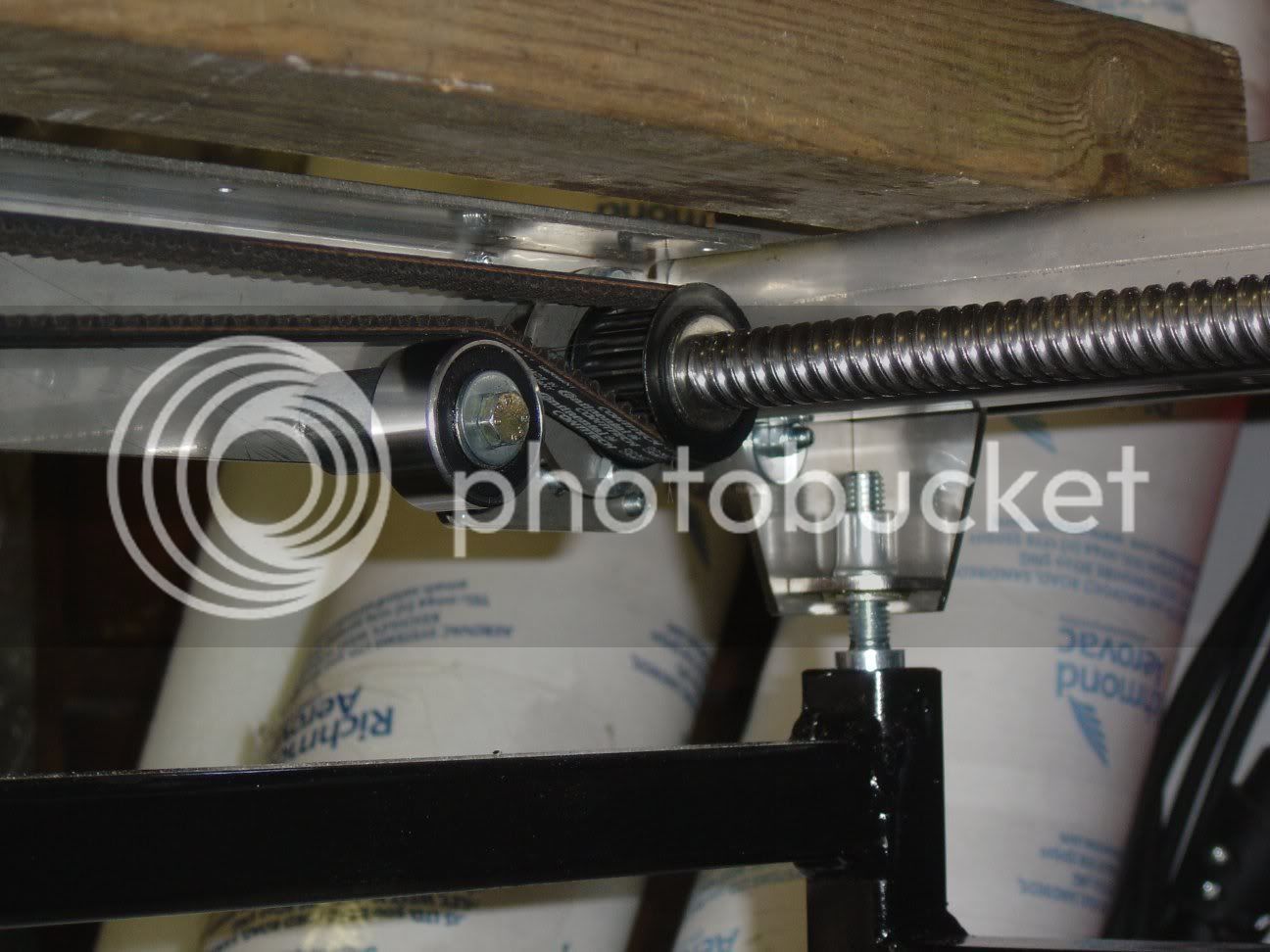
What I'd like to ask the many experienced folks here is if anybody can comment on the idea of using a Turnigy SK3 6374 168kv (with external hall sensors, obviously) and a two stage reduction with a 15mm GT2 timing belt as the first stage, and a #35 chain as the second stage. I'd use a 15mm wide belt, and provide tensioning ability for both the belt and the chain independently.

Here is the trouble- It seems that timing belts are really complicated, because I've been all over the Gates website, and I haven't found a good reference on figuring out exactly whether or not this size of belt is strong enough for my load. I also called the sales rep and asked for assistance. He took all of my information, promised to get back to me and then never did. I work as an engineer during the day and this is just a side hobby for me- I've rarely had such trouble with a supplier! I've also never had occasion to use one of these belts before, so I just don't even have a "gut" feel for it- that's why I'm asking here.

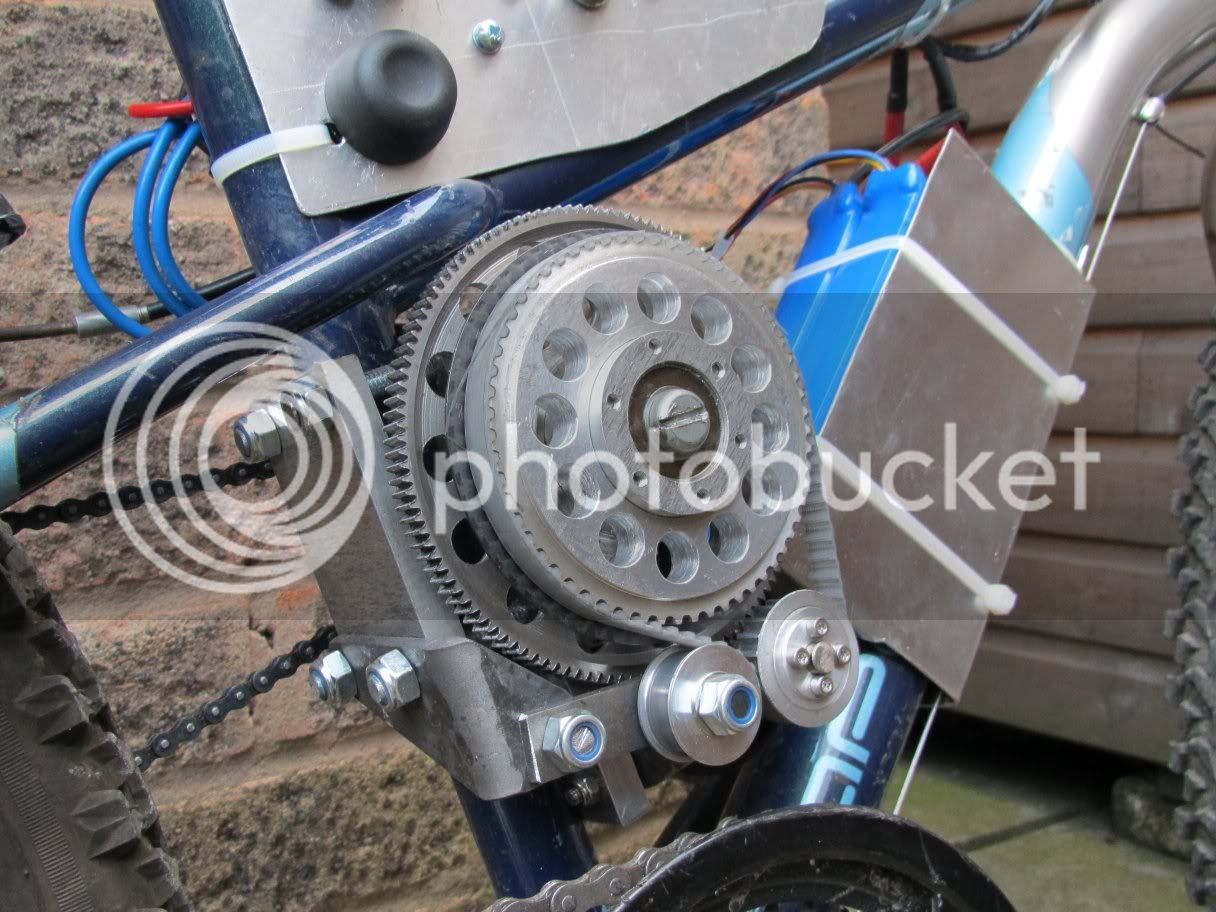
Anyway, the plan is to mount the motor on a standoff and use a coupling to attach the shaft to a supported 15 groove GT2 sprocket, which would drive a 50-ish tooth sprocket with a 15mm wide belt. The large belt sprocket would be on a jack shaft driving a small #35 chain sprocket which would drive this 60 tooth sprocket wheel combo for whatever ratio gives a top speed between 7 and 9 mph. It looks like 16:1 at 24V is OK, and 20:1 at 36V is not bad. From a design flexibility perspective it looks like I can experiment a lot with changing the ratio between the chain sprockets and adding and removing chain to get the right length.

I'd expect to take the Turnigy SK3 6374 up to 6,000 RPM at 36 volts, and feed it no more than 75 amps. At 16:1 I'd see a thrust of about 120 pounds, and at 20:1 it could be pushing 150.

Sorry if this was the most roundabout possible way of asking this, but the TL;DR is- does anybody have experience or reference materials to tell me if a 15mm wide 5mm GT2 belt survive 6,000 RPM and 37 ft-lb input on a 15 groove sprocket while driving a 50 groove sprocket?

Thanks! :D
 
As I continue my search, I came across http://www.electricycle.com/ where a guy named Eric Peltzer (is he on this board?) made a bike that's similar to what I'm talking about. I see that he's using a 25mm wide belt for a similar reduction to what I'm considering. His controller is 180 amps, and although I'm having a little trouble seeing exactly where he says it, I think he's throwing at least 100 amps to the motor on occasion. According to a spreadsheet I found online while searching for his motor (Scott 4BB-02488), it gives 9.8 in-oz/amp, so that sprocket (looks like 21 grooves?) is seeing about 60 in-lbs of torque; nearly double what I'm talking about. For that reason, I'm going to go ahead and say that at least in terms of peak forces, the 15mm wide belt that I'm proposing would probably be no worse than what he's got going on. He said it's been really reliable, so I like the sound of that.

One difference is that if I ever go to 36 volts, running at nearly double the RPMs. Most of my use is in hard acceleration/deceleration over and over, so I'm hopeful that this won't be the kind of sustained high speed/high torque load that gives a belt thermal troubles.

SO- that's my best shot tonight at answering my own question (if you can call reading a guy's website answering it myself... :roll: ). I guess the only new thing that I'd like to ask here, if folks think I might be on the right track so far, is what you think of those Shaft-Lock timing belt pulleys- specifically the glass filled nylon ones. I'm thinking of going metal for the small sprocket and shaft-lock metal-core nylon for the large one. It could save a couple pounds, and I think I can get away with it.
 
joec said:
Sorry if this was the most roundabout possible way of asking this, but the TL;DR is- does anybody have experience or reference materials to tell me if a 15mm wide 5mm GT2 belt survive 6,000 RPM and 37 ft-lb input on a 15 groove sprocket while driving a 50 groove sprocket?
Not if you really mean 37 ft-lb.................

3.7 ft-lbs would be ok. :)

http://www.gates.com/brochure.cfm?brochure=12692&location_id=19239
 
So where can I get one of those one-pound RC motors that will do 37 foot pounds at 6000 rpm? :lol:

I definitely meant inch pounds, not foot pounds, so only 3.1 ft-lbs. :oops:

Thanks Miles!
 
GT2-5mm pitch and HTD-5mm pitch are both OK to use at 6,000-RPM, the small pitch allows a small motor-pulley. Which one you choose will likely be driven more by the availability of finding a pulley you like that is off-the-shelf, rather than a custom-order.

15mm wide is common, but if the belt starts skipping the belt will be damaged rapidly. To improve torque-holding capability, you can raise the tooth-count on the driving pulley, or widen the pulley and belt. 20mm wide and also 25mm have been used.

For a primary reduction using chain, #25 is the less expensive option, and #219 kart chain is the more expensive and stronger option, though I am of the opinion that the higher-quality #25 is fine for a high-RPM/low-torque bicycle primary. Both have a 1/4-inch pitch-distance between the pins, so they have twice as many pins compared to bicycle chain (#41/#410/#415). Do not use the narrow-link 9-speed bicycle chain, and the wide/heavy-duty #415 cannot be used on a derailleur, only a single-speed.

For a secondary reduction (or a final driveline) the 8mm pitch is stronger and has been used in both GT2 and HTD. However the larger teeth (wider/deeper), will limit the size of the smaller pulleys to a larger size than the 5mm-pitch.
 
Hi Joec,
I use 9mm wide 5mm pitch HTD pulleys/belt on my ebike and it's pretty reliable - I'm on my 2nd belt now over about 1000 miles. To be honest the 1st belt didn't wear out, I ruined it by running it on the flange by mistake for a short while... I use an idler to tension the belt and increase wrap on the smaller pulley
queerbox.jpg

I've had no problem just using the motor bearings, I use a taper-lok arrangement to fit the pulley onto the motor shaft - honestly it's dead easy if you have a lathe & 1000 miles on with no problems from that quarter.
I remember similarly being frustrated trying to pin down definitive design information on the toothed belts & eventually resolved just to make one & see how it went. It's still going just fine! Your motor is 30% or more bigger than mine so I'm guessing 1 15mm wide belt would be ample (withe the same diameter pulleys as me)
cheers
Bob
 
Spinningmagnets- thanks! I will look around to see if I can find pulleys for a 20mm belt. I will probably stay with chain for the last stage of reduction since I can buy the wheel with sprocket and bearing cheaply, then I just have to support a stationary axle. The #35 chain seems really popular, and from what I've read it's more than strong enough for the torque in the last stage of this setup.

Bobc-thank you for sharing your results! Breaking a motor or two isn't so costly in comparison to everything else in this project, so maybe I should just use taper locks like you did, and go to couplers later if something breaks. It would definitely help me get it done if its simpler. Let me tell you- I am going to have a lot of fun tooling around in this thing trying to break it.
 
bobc said:
Hi Joec,
I use 9mm wide 5mm pitch HTD pulleys/belt on my ebike and it's pretty reliable - I'm on my 2nd belt now over about 1000 miles. To be honest the 1st belt didn't wear out, I ruined it by running it on the flange by mistake for a short while... I use an idler to tension the belt and increase wrap on the smaller pulley
queerbox.jpg

I've had no problem just using the motor bearings, I use a taper-lok arrangement to fit the pulley onto the motor shaft - honestly it's dead easy if you have a lathe & 1000 miles on with no problems from that quarter.
I remember similarly being frustrated trying to pin down definitive design information on the toothed belts & eventually resolved just to make one & see how it went. It's still going just fine! Your motor is 30% or more bigger than mine so I'm guessing 1 15mm wide belt would be ample (withe the same diameter pulleys as me)
cheers
Bob


i think you could help on this thread m8 ,, http://www.endless-sphere.com/forums/viewtopic.php?f=28&t=42785

we have been trying to work out a belt system for ages for the GNG MID MOUNT KIT ,,

i think they would love to hear about your set up ,,
 
Whoa whoa whoa- back up! I just read for a minute but it sounds like this GNG motor is a 67 rpm/v inrunner with sensors and capacity to average 1000 watts... Am I missing something? I beleive i also read that its impedance is about 73 milliohms. This sounds like a way better motor for my project! I was very interested in the Golden BLT-800, but someone measured phase resistance for me and found that (at least for the 650 watt version) resistance was 0.40 ohms- way too high to get decent performance if I wanted to give it a shot at lower voltages.

I'm off to read a lot more about this GNG stuff! :mrgreen:
 
If you have access to powerchair motors, you mgiht also look around for this BLDC unit:
http://www.endless-sphere.com/forums/viewtopic.php?f=30&t=32838
as it can be run off regular ebike controllers once you add halls to it, or off a Sevcon (and maybe some Kelly) controller with the existing Sin/Cos encoder output, and I expect it could deal with quite high speeds and power loads, and bolt the wheels directly to it.

(or use it as a middrive as I plan to, but I'll be using single reduction chaindrive power transfer).

(and if you *can* get hold of them really cheap, I'd be interested in more of them myself--a pair of the same unit would make a nice heavy-cargo trailer power assist!)

Alternately, there are some BLDC hubmotors you could lace into wheels of your choice that have single-ended axles, and could be mounted in place of powerchair/wheelchair wheels on many chairs, though you might have to make mounting brackets for some of them.
 
I looked at threads about this with some curiosity... I'm familiar with this motor, and it t works reasonably well in some of the chairs that are being used for the sport. However, in my experience the controllers quickly enter thermal rollback. These motors seem to have an integrated temperature sensor, so even though I've added cooling fans to the existing 100 amp motor controllers, they just don't survive long before output is throttled. Right now I have one or two of these chairs being used as loaners for folks who don't really have anything else to play in. Unfortunately there is something wonky in the wiring or sensors (or something) that causes the chairs to need to be power cycled at random intervals. It's frustrating, but hard to troubleshoot. I don't have any way to really interface with controllers over a PC, so I'm in the dark on trouble shooting.

I don't pay much attention to this motor because I don't have ANY source for them that's less than about $1500 each, other than pulling them out of the odd chair that gets donated. I don't have any good ideas for controllers, either. We use two motors per chair, and the controller that comes with the chair does 100 amps per motor, and this is just barely adequate. I'd need a controller to do more like 150 amps, and a way to get the heat out of the motors. It could be a BEAST then, for sure- but I'd need to figure out controllers. I can't just use a Kelly or Sevcon- I'd need a pair of them with a wig-wag center-neutral throttle, and some sort of supervisor board to do steering mixing to allow the chair to be driven with a joystick. That's a royal pain in development work, mostly because the standard of safety has to be very high.

I need to be able to have around 120 pounds of thrust from 0mph to at *least* 3mph, and a top speed of over 6mph, and I need to be able to take off like that at least four or five times per minute for an hour. I also need to be able to do this in reverse, and I need to be able to smoothly modulate the speed around the zero point with no delay. This is the biggest reason that I haven't been happy with any of the E-bike hubmotors- I just don't think they can give me that kind of repetitive high torque action. It seems like everyone uses E-bike motors to take off, then cruise at speed- not jump forward ten feet at full throttle then regen-brake to a complete stop.

Overvolting the linked hub motor with a chain reduction is an interesting idea- maybe something I could do with my existing stock- but my gut says that unless I can also pull off a lithium system, it will be too bulky. I'll definitely chew on it, though. Thanks for bringing it up.
 
Doh...I forgot that you'd be using a joystick type control for two motors, and that you need fast hard reversing capability. However, you could still do it, assuming the cotnroller is programmable for max reverse power (some aren't, and only do a percentage of forward power). Would take some mechanical kludging, but you could fix up a two-pot spring-centered joystick and some op-amps and comparators and/or logic gating, so that when a pot reads up to half it's output it turns on reverse for that controller, and outputs up to the full throttle range, reversing the voltage output of the pot so zero pot output is full reverse throttle. Then above the half-output line it turns off reverse and scales the output for the forward throttle voltage. Use a small deadband in the middle to ensure a parking stop.

Active regen braking could also be done with some controllers, so that as the throttle is pulled back while it's still moving faster than the throttle is telling it to, it actively brakes to slow the motor down. Not all controllers do that (most don't, I think), but some do, or can be programmed to.

It might be easier to do the electronics of throttle conversion with a small MCU, but I don't program so I would build it analog. ;)


(I was going to say: remember that for controllers all you have to do is install hall sensors, which is super-easy (even I managed to do it right! :lol:) and then hook it up to a typical cheapish ebike or scooter controller. Use better (more expensive) controllers like those Zombiess, Lyen, or Methods makes and sells in the Online Market section for higher power levels. but you can ignore that now )

Getting heat out of the motors...they're not sealed, and could easily be vented. Easiest way is to duct air into the mounting plate box with a squirrel-cage fan (you'd need to machine a hole to input the air, and if you aren't using the brake rotor in there, you can take it out to make airflow better). If you can, put holes in the tower inside of the stator, or out where the outer rotor bearing sits, Then air will flow thru/around the stator and coils, and between the stator lams and magnets, before passing out of the motor under hte rotor edge. It ougth to do a pretty good job of cooling it, if you can move enough air. Would be noisy, but I knwo that I could live with it. :) Just use a thermal sensor (you can add it when you add the halls) to control fan speed.


As for availability, well...I can't help much with that, other than to suggest things you probably already know, such as checking with various other powerchair repair places, old folks homes, retirement centers, hospice, or other types of places that might use them (in or out of your area) to see if they are scrapping any chairs with tehm on there. Keeping an eye on Craigslist or Freecycle.org for your area might help too. (people do sometimes give away such things...I have a whole powerchair I got when someone passed away and didn't need it anymore, though its' the old brushed gearbox type, and a regular wheelchair the same way, off Freecycle).

Given the pinout for the motor appears to include a serial I/O connection, I'm nto surprised there's a thermal sensor in there, too, to tell the controller when it's too hot. If you can locate the actual sensor and tap into it, you could use it for the fan control.


But all in all, I guess it's more complicated tahn it seems, to use two motors witout the original controller.


If you could use higher voltage on the original controller, you could just double the voltage, and gear the otuput down, and probably be able to do what you want, with active cooling of the motors and controller(s).

Brushed motors will get hotter at higher voltages because of brush arcing, but brushless stuff doesn't do that. :)
 
amberwolf said:
(I was going to say: remember that for controllers all you have to do is install hall sensors, which is super-easy (even I managed to do it right! :lol:) and then hook it up to a typical cheapish ebike or scooter controller. Use better (more expensive) controllers like those Zombiess, Lyen, or Methods makes and sells in the Online Market section for higher power levels. but you can ignore that now )

Do the GNG motors need me to add hall sensors? I've seen a lot of threads about the trouble involved in adding and configuring sensors on outrunners- the GNG motors are a lot more attractive if they already have sensors installed. At 0.073 ohms and a kv of 67, I could gear them down with a ratio of 7:1 and get great performance with the Roboteq dual channel 75A brushless controller at 24V. Even better performance with a higher ratio and a different ratio! I could potentially get 150 pounds of thrust all the way until 7mph at 36V and an 8:1 ratio. Don't forget I have two motors, so that's actually 300 pounds of thrust. The hard part is keeping the wheels from slipping!

I understand what you're saying about putting together E-bike controllers to work, but I need a lot of reliability and ease of fine tuning the response. The Roboteq gives me that with digital communications to the joystick, a lot of parameters that can be configured on the fly, and selectable response curves. It's probably not interesting to anybody here because the price per watt is far more than folks are likely used to paying- but it looks like the GNG motors would be the kind of load that would never blow this controller up.

Thanks for sharing so much about the wheelchair motors- I've never taken them apart, and I'll definitely follow your lead if the chair ever acts up enough that we think of scrapping it. If we actually do scrap it, it will probably be a problem with the digital communications more than anything you'd care about, so I'll bring them to the forum to see if anyone wants them. Hopefully, though, I'll just make some kickass soccer chairs :D
 
joec said:
Do the GNG motors need me to add hall sensors?
I don't know. That you'd have to poke around the various GNG threads to see, but I expect they already have them in there.

If we actually do scrap it, it will probably be a problem with the digital communications more than anything you'd care about, so I'll bring them to the forum to see if anyone wants them. Hopefully, though, I'll just make some kickass soccer chairs :D
Hopefully--but if you do end up getting rid of any of those BLDC powerchair motors, I'd definitely be interested (just keep in mind I almost never have any significant amount of money to spend on such things). Others here on ES that do have money probably would be interested in them, too--perhaps even those with access to Sevcon and similar sin/cos capable controllers, which could directly utilize the output from this motor.
 
I've been thinking about this scheme, and this is what I have so far. I want to use a 2"x4" 6061 aluminum tube with 1/4" walls as the core to hold everything, and use a Turnigy SK3 6374 with a small timing belt sprocket mounted directly to it driving a jackshaft with another timing pulley on a 1/2" shaft to run a small #35 sprocket driving the 60T sprocket that's mounted on the hub of the Northern Tool wheel assembly. The wheel will sit on a 0.75" dead axle using its included bearings.

Here's a top view:

top.PNG
 
Sorry, my lousy hotel wi-fi deleted a few posts that I made that were better written with inline images and a concrete line of thinking... I just wanted to post this pic while I was thinking about it.

The overall width is kind of excessive, even for a wheelchair, so I'm looking at milling custom low-profile bearing mounts to support the jackshaft, even though I can get mounted bearings cheaper. Here's a side view showing the total wrap that I could get- I think I can get close to 5:1 inside the rectangular tube with the timing belt (5mm pitch and near 6:1 on the #35 chain reduction.

side.PNG

And here's a front view-

View attachment 1

Roughly isometric-

iso.PNG

So does anybody see any obvious pitfalls, n00b mistakes, subtle traps, or poor assumptions? :D
 
spinningmagnets said:

Thanks! That's probably a more robust motor than the Turnigy outrunner. I'm trying to remember if there was something other than price that was pushing me away from the GNG and toward the Turnigy. I think that price was likely the biggest factor- I'm not crazy about paying for GNG kits and throwing away a bunch of parts just to get the motors. I suppose I should email to ask if I can just buy the motors on their own.
 
Joec - you'll need adjustment to be able to tension the final chain And the belt - belt probably best done with an idler as it increases wrap on small pulley
 
Thanks, Bobc- I guess I can make a provision to try an idler as well as slotting the motor and wheel mounts. I'm just thinking about how that idler is going to have to be strong.

The good news is that I got word back that I can get the 450 watt 48V GNG for $118 plus shipping. This is going somewhere!
 
joec said:
Thanks, Bobc-

The good news is that I got word back that I can get the 450 watt 48V GNG for $118 plus shipping. This is going somewhere!

THat sounds cheap ,, the only place i can buy them in the uk charges
£265.00
+ £15.00 postage
 
Joec - ust a quickie - how I made the idler on a CNC router I built - the bearing shaft is not in line with the bolt hole so you rotate the body to adjust - dead easy & rock solid
tensionser.jpg

belttensioner.jpg
 
Back
Top