Upload Your Circuit Schematics & Requests Here...

Beagle123 said:

Hi all:

I'm trying to devise a circuit to test individual cell voltages. I hope to use this 16 channel multiplexer to cycle through each cell and report each voltage to a microprocessor chip:


http://focus.ti.com/lit/ds/symlink/mpc506.pdf

Does anyone have any ideas?

Ok, glad to see your on that trail Beagle. I've been thinking along the same lines. I don't see any way around the voltage divider, but if there was a multiplexer chip that could pass full pack voltage, you could switch each cell to a differential amp to get the cell voltage referenced to ground.

With voltage dividers, accuracy might be an issue, but then do we really need 1mv accuracy?

If each cell had a A/D converter and communications chip, you might be able to send voltage data over a buss. I think they make chips that do that too. You'd have to level translate the data output to the buss somehow.

I'm still looking for suitable parts and thinking about a topology for this approach.

One workaround for the divider accuracy issue would be to calibrate each cell in software after the circuit was built, so you could use cheap, high tolerance resistors, then calibrate each cell with an expensive Fluke meter afterward. Of course this complicates software, so I'd like to avoid that if possible.

EDIT: I decided to create a new thread for this here:
http://endless-sphere.com/forums/viewtopic.php?f=14&t=3486
 
Hi well I need a lot of help with the design of this charger using Dc Dc converters as single cell chargers.

I am planning to use 80 M1 cells basically arranging them four packs of dewalt batteries
10s4p%20Sub-Packs.gif
and then running 14 gaug wire from the balancing tabs to make 10s 4 p pack so to speak.

build two of these . the charging set up is going to be the bigger challenge for me these tyco 3.3 modules are capable of performing higher than rated according to their datasheethttp://power.tycoelectronics.com/BinaryGet.aspx?ID=02c39fa8-b980-4ed3-ae07-0b21ba259203
so i am learning that using a 10 k potentiometer the output could be adjusted to produce 3.6 volt for example to charge each cell to that voltage.
( not sure but i think i need a 10k pot for each module 20 exactlly)

http://endless-sphere.com/forums/viewtopic.php?f=14&t=2824
there is where i read about this idea and i here i am giving it a shot i trust Stephane the doc to know . he is currently working on his set up .
the innput for these modules i think is optimized at 48 volt so i would need somthing along these lines

file.php


the balancer wire since they are isolated they can be wire like Gary Goodrum's single charger set up thanks to everyone for their input BTW
Battery%20Balancer%20Plugs.png


and this for the opposite end where the charger hooks up to the balancing wires


there there is what i am trying to do i first of all i have to charge each pack to its max these are supposedly new packs once i receive my mega power 960 i will slow charge initially perhaps some test cycles and then start assembling the packs


any ideas fo rthe balancing harness plug types? anderson 30 amps there is gonna be 11 wires?

that enough for now please chime in thanks a lot

efreak
 

Attachments

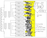
  • 10-Cell Boost Charger Circuit(ED).PNG
    10-Cell Boost Charger Circuit(ED).PNG
    86.7 KB · Views: 7,709
If the individual dc-dc converters have the right voltage output, you won't need the voltage detectors on each cell.

In your diagram, the two main + and - connections to the batteries need to have heavy wires and contacts, but all the taps between cells will normally carry a tiny fraction of the total current, so you could use smaller contacts and wires. If the batteries are exactly balanced, the current in the tap wires will be zero.
 
HI ya I won't need the voltage regulators thanks this for illustration but ya will i ned the pots wired full time on each module?

and should i chrge the batteries before using dewalt charger afew times ??
some people suggest to initial charge them at low rate e.g. 0.3 rate amps to make or a longer battey life

efreak
 
Hey guys i need some help to build a mosfet driver. I want to drive 10 mosfets at the same time for
on/off function. Looking for a single driver to drive them all together for simplicity. The mosfets will be
kiiling the power to the balancing leads of this lithium pack inside the front wheel. Having live wires
hanging out is to dangerous. i could just install fuses at each cell but if one of them short out replacing
them is a pain in the neck. Here is the picture of the wheel. I have removed the dewalt battery balancer
in order to use the bantam charger with balancer. the original wavecrest charging mosfet used for on and
off is the irfr2407 n channel 75volt and 40amps.
http://pdf1.alldatasheet.com/datasheet-pdf/view/68570/IRF/IRFR2407.html
 

Attachments

  • front wheel charging.JPG
    406.2 KB · Views: 5,522
I found this driver used in battery powered devices. This driver only comes in umax size so very small, but
seems as this can be controlled by a small momentary pushbutton. So how can i connect this to feed and turn on
all mosfets at the same time.

http://pdf1.alldatasheet.com/datasheet-pdf/view/72860/MAXIM/MAX1614.html
 
The datasheet indicates the driver is only recommended for systems up to 26v, with and absolute max of 30v. It also needs at least 5v to run, you'd need to feed each one from 2 or 3 cells to get enough gate drive.

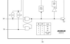
Rather than push on / push off, you can wire the driver to be positively on or off when the right signal is present on the inputs. There's a truth table in the datasheet:
MAX1614 inputs.jpg

It looks like you could tie up to 26v worth of batteries into set of these on a common ground and parallel the inputs. Since your pack is more than that, you'd have to split the inputs and figure out how to drive both of them at the same time.

Optocouplers would be a good way to do that. Have the inputs wired to be normally off, then use optocouplers to turn the taps on. The drive for the optocouplers could be from something on the charger, so the taps automatically turn off when you unplug.

What about using PTC's on each tap? (Those things that are like self-resetting circuit breakers). I've seen some automotive type self resetting circuit breakers that work well also. You might get a spark, but no fires or damage.

Your connectors should be protected against making accidental contact anyway (female contacts on battery).
 
Here are a couple of pictures of the Batteryspace 36V/40A BMS:
http://www.batteryspace.com/index.asp?PageAction=VIEWPROD&ProdID=3558

Front:
boardFs.jpg


Back:
boardBsl.jpg


For a bigger view of the component side of the board, with the components identified:
http://www.az123.com/BMS/boardFcomp.jpg (1.2Mb file)

There were no markings on the little surface mount capacitors, and I don't have a capacitance meter, so I can't help any more there.

I guess I should add that I had problems with the one I tried to use... More info on that here:
http://endless-sphere.com/forums/viewtopic.php?f=2&t=3649&p=53856#p53856
I haven't figured out yet if it was because I messed up the wiring, a bad board or an inherent design flaw.
 
Anyone has a manual or schematic for a L'Eco Prima controller. It is a pedal 1st sensorless brushless controller. It has a few open connectors and I am trying to find the brake input.
Thanks,
 
brake input should be the one that causes the motor voltage to go low (zero volts or close thereto) when you short the terminals.
 
I understand, but before shorting terminal together, I would like to know which 2 to short.
There is a red 2 pin and white 5 pin connectors open.
 
I looked on the web for some specific Prima info, and couldn't find anything, so maybe try an email to the company (http://www.powerbikes.com) as a first resort and call the various dealers on the web. Assuming that doesn't work, all the brake connectors I've seen on other controllers are two-wire, so measure the voltage first (make sure you're not seeing full battery or motor voltage) and then try shorting the two-wire, maybe through a 2k power resistor just to be safe. See what happens to the motor voltage when that happens.
 
Hello,
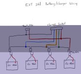
I am unable to figure out how the charger does it with these connections, but it somehow charges each of the four 12 volt lead batteries individually and simultaneously. Attached is a diagram of the EVT 168 battery connections and charger socket connections. Hopefully this will be of use to someone. If anyone can explain how it does this without shorting, let me know. I'd like to apply a balancing charger to ebikes.
-Colin
 

Attachments

  • EVT 168 Charger Connection.jpg
    EVT 168 Charger Connection.jpg
    67.6 KB · Views: 3,110
carbon.nanotube.capacitor said:
If anyone can explain how it does this without shorting, let me know. I'd like to apply a balancing charger to ebikes.
-Colin

It uses a separate isolated charger for each battery. This is a good way to balance the batteries.
 
Hey Fechter, Thanks... But how does each charger remain isolated, even when the batteries are connected to each other? Maybe I just need to let this simmer in my skull for a while. Right now all I can think of is how a positive battery terminal will inevitably be connected to a negative charger connection, same for the negative battery terminal of another being connected to a positive charger connection... Would that not put an end to the isolation? Hmmm.
 
Schematic for Currie 24V Charger

Postby donob08 on Mon Jun 16, 2008 3:34 pm
Schematic for Currie 24V Charger
My second (for second battery) Currie 24V, 2A charger, Model CC2415 got damp left in pannier, unpowered, hard rain found its way in. I've ordered a Soneil 2404 S battery charger from NYCEWheels but would like to fix this one for the interim 2nd day air and to have as a spare. It is R6 that is burned beyond recognition. I need its value, for a start. I'm an Electrical Engineer. I can figure it out. I'm lazy and busy.

Any help would be appreciated.
 
carbon.nanotube.capacitor said:
Hey Fechter, Thanks... But how does each charger remain isolated, even when the batteries are connected to each other? Maybe I just need to let this simmer in my skull for a while. Right now all I can think of is how a positive battery terminal will inevitably be connected to a negative charger connection, same for the negative battery terminal of another being connected to a positive charger connection... Would that not put an end to the isolation? Hmmm.

Yes, they will no longer be isolated from each other after you connect all of them.
The problem is chargers that have one output pin connected to the AC line ground. If you put two of these in series, the ground connection shorts out one charger and smokes it. Each charger output must be isolated from the AC ground to prevent this loop. With an isolated output, you can put multiple chargers in series, just like you put batteries in series to get a higher voltage.
 
New YK42-3 controller

Just got a new YK42-3 (Brushed 36V) YiYun controller from TNC. (don't ask why I had to get another one :cry: )

Same basic components as the one I dissected (with Fechter's help, of course) on pages 12 & 13 of this thread; 3435 MOSFETS, 20100 schottkys etc,
but there are a few changes worth mentioning:

First of all, the case is noticeably longer: 7 inches as opposed to the 5 inches of all my other YK42 model controllers (same 2" X 3 1/2" in the other dimensions).

There was plenty of waste space in the box before.... Now there is almost enough to put two controllers in one box.... Or plenty of room to add various extender boards for extra freewheeling diodes and capacitors if you should want to do something like that.

There are also two new wires and a connector sticking out... Yellow and black; I'll ask TNC, but until I hear otherwise, I'm going to assume that they are for a brake switch, since some of the other YiYun controllers use yellow/black for that purpose. The board on the older controllers have the same solder point open, so it is pretty safe to assume that you could retrofit them to us a brake switch (or whatever this is).

And the thing I really like is that the power wires have been REALLY beefed up: The new ones are nearly 8Ga... they measure 3.1MM diameter, which makes them not quite 8, but much bigger than 10ga. There is a color change too... The Motor negative wire is blue instead of green.

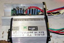
Here are a couple of pictures:
#1: Comparing case sizes:
NewYK42-3A.jpg

#2: Throttle and new wire connection points:
NewYK42-3B.jpg

I don't know if they are all coming like this from the factory now or not... I'm pretty sure this is a rebuilt one... There is some evidence of 'the magick smoke having leaked out" down around the area where the voltage regualtor is.
 
Heard back from TNC: (Prompt customer service, as usual):

You are correct the Yellow and Black wires are for the brake kill switch.

If you do not plan to use the brake switch, then you can just leave this connector open.

I have also attached a new wiring diagram that shows this connection.
 

Attachments

  • YK42-3 Controller Specification 1 Page.doc
    91 KB · Views: 617
Thanks for the report. Maybe they're learning from us... :twisted:

The larger case might have room for a dc-dc converter inside.

I'd like to make a sticky post for YK-42 controller info, since quite a few people use them. Look for that coming soon (I hope).
 
fechter said:
...The larger case might have room for a dc-dc converter inside.

Plenty of room. I could stick ten of these:
http://cgi.ebay.com/In36V-72V-Out-1...erter-Module_W0QQitemZ250264527762QQihZ015QQc
in there, and still have room for bigger capacitors.

Although in general, Despite the fact that the controller on my dual hub motor Mk1 had a huge controller box containing two controllers and three DC-DC converters, I'd rather have smaller OEM controller boxes; Easier to find places to mount them and stay sort of stealthy.

Although two minutes with a bandsaw and you can trim these larger cases down to the original size if you do want it smaller.
 
fetcher (& company),
Perhaps I could tap your wisdom for a simple (for you) schematic? I posted a RFO on 'V is for voltage' but saw this knockout technical stuff here.
I am assembling my BD36/LiFePO4 36V-20Ah/Townie. There is no key, just an on/off switch on the 35 amp controller, no fuse link or BMS except on the charger.
I want to incorporate a watt meter, switch and in-line fuse. What amp fuse keeps everything safe and where does it go? :?
Any little drawing or advice would be so appreciated. I so don't want to hurt the expensive battery or melt something.
Thanks
 
Sorry I missed your post earlier.

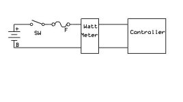
Here's the basic setup. It doesn't matter if the fuse and switch are on the positive or negative side. They don't have to be together either. Just anywhere between the batteries and the watt meter (assume something like a Wattsup).

For a 35 amp controller, I'd go with a 40 amp fuse.

Not sure how a LiFePO4 is going to survive with no BMS. What happens if one cell goes low on discharge?
fuse and switch setup.jpg
 
hi guys. First off I apologize if this has been posted elsewhere - I'm browsing on my phone which makes searching a real trial! I have the setup as described above (detail: 36v ecrazyman shenzen controller and trigger controller, 36v 250w Suzhou 8fun hub motor, 36v 10ah battery from JimmyWu offa ebay. Rick off the forum here has also kindly provided me with a kit of his fabbo leaf switch brakes). Now I'm not a total amateur but none of these items have come with any suggestions as to how to wire them up. Has anybody here done it and have a diagram they can post? If not, once I finally get all my components together in the same country (!) could somebody "join the dots" for me if I were to post a picture?

I've read the warnings about blowing a controller and I don't want to waste another 6 weeks waiting for replacement parts to arrive!
 
Back
Top