Upload Your Circuit Schematics & Requests Here...

Wish I could contribute here... but at least let me post a link to someone elses EV schematics? Various circuits from Mark Hanson who frequents the EVDL:
http://www.evdl.org/lib/mh/

...stuff like:
Battery scanner individually and simultaneously monitors up to 24 batteries in an EV's pack
Inverter converts 24-72vdc to about 1400 watts of 120v or 240v 60Hz AC, for EV air-con and other accessories

And promised soon:
"I made some battery equalizers for my Li-ion T-sky batteries using a simple PWM (1kHz) feedback technique to modulate the power shunt resistor so the darlington transistor doesn't fry (like on other storebought versions). It's designed for a 2A max shunt current and am using on T-Sky yellow batts set to 3.8V. The charger is a standard dv/dt=0 charger so it shuts off when the voltage stops rising for an hour. I took a turn off the secondary to reduce the taper current to 1A which keeps the balancers from getting too hot. I also found that when discharging they stay fairly close in voltage since they were equalized on charge (solar boat 16 cells 52.8V at 3.3V per cell) final charge is 3.8 x 16 = 60.8V"

Tks
Lock
 
We need battery and motor temperature displayed on our CA's.
Justin, When will we see that?
 
hello all, I need some basic electronic help.
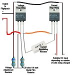
I need to build a parallel lipo charger, and I found a pretty simple solution on rc groups, using lm317's
here the link: http://www.rcgroups.com/forums/showthread.php?t=130567
and the schematic charger.jpg
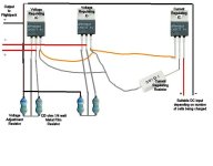
I'm wandering if I can modify the system for multiple cells at 4.2v each...
something like thisparalelcharge.jpeg

It would charge slow (lm317 is 1.5amp max ) but get the cells balanced correctly
do you think it could work like this?


thx
 
This falls under the "Request" portion of this thread. Your help is greatly appreciated.

I'd like to configure my setup for 3 options (with hopefully minimal time necessary to switch)...
1. Series - 72V20Ah - for :mrgreen:
2. Parallel - 36V40Ah - for increased range
3. Single Pack - 36V20Ah - remove one pack for lighter load

I have two 36V20Ah Headway Packs (with the 38120 10Ah cells (5C), each pack with its own BMS). I'm using a Xlyte 7240 12-fet controller on a rear hub X5.

Thanks.
 
I have been thinking to add a 'spark' reducing battery connection circuit. (A soft start of sorts) Ive come up with this.. any comments.

Operation: The keyswitch supplies power to controller through 400 ohm resistor to precharge the controller capacitors. Also voltage from keyswitch is supplied to time delay contactor coil K1. After 2 secs contactor coil closes contact K1-1, effectively bypassing pre-charge circuit. Contactor is held on thru keyswitch. When keyswitch is turned off, contactor drops out and power is removed. Diode in series with the 400 ohm resistor prevents power supplied thru the contacter contacts or stored charge in controller from holding the time delay contactor on.
 
I don't think you want the keyswitch to carry your actual motor current, unless yours happens to be physically large enough to be rated for that kind of voltage and current.

Typically the keyswitch would turn on the contactor instead. Some vehicles (like golf carts) have a three position switch, for OFF, Precharge (what you are wanting to do), and RUN.

The OFF key position disconnects the contactor completely.

The Precharge key position switches power (usually thru a separate contactor, but sometimes directly) on, to a resistor like your 400 ohm, which then passes power into the controller to charge the caps.

The RUN position switches power fully into the controller, bypassing the resistor. This is usually done with a contactor, separate from the precharge contactor (if there is one).
 
I think we are in agreement! I've added explanation to original post. Maybe a second relay is needed if the keyswitch isn't up to it, although I think increasing the delay and resistor size would also help.
 
lalaland said:
I have been thinking to add a 'spark' reducing battery connection circuit. (A soft start of sorts) Ive come up with this.. any comments.

Operation: The keyswitch supplies power to controller through 400 ohm resistor to precharge the controller capacitors. Also voltage from keyswitch is supplied to time delay contactor coil K1. After 2 secs contactor coil closes contact K1-1, effectively bypassing pre-charge circuit. Contactor is held on thru keyswitch. When keyswitch is turned off, contactor drops out and power is removed. Diode in series with the 400 ohm resistor prevents power supplied thru the contacter contacts or stored charge in controller from holding the time delay contactor on.

Commenting on my own post :? It seems DC contactors dont come with time delay options. DC contactors are also expensive and bulky, and use around 15W just to stay operated. Two 24V DC auto relays in series should also work - just need a timer circuit - or the other option I might give a go is a DC solid state relay. See http://www.hongfa.com/products/product_01.php?id=284&disp_type=&product_type=4 The SSR should provide soft start and requires very little current to operate, and is reasonably cheap. Disadvantage - some on resistance, hence wasted power and heat. Some models are quoted as low as .007 ohm max on resistance which is good, some of the others not so good.
 
As for the cost, there is recent thread in the for sale section for some Kilovac contactors. IIRC, Methods bought a few and has some for resale. Check the thread to be sure.
http://endless-sphere.com/forums/viewtopic.php?f=9&t=15094
 
I entered this question in another board, I think this is where it should go.

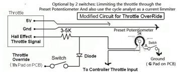
I have a cycle analyst and would like to use its th pad connected to my throttle signal to use it for economy sttings and current draw settings etc.

I also have the legal isue of speed in the Netherlands. So I would like to use a Preset Potentiometer that will reduce my speed with a preset speed of lets say the legal 25kph.

So this is switch 1 mounted on the cycle analyst. = Switch for a quick legal fix!

The other switch would be used to drive on an economical way using the limmiting function of the cycle analyst not just for speed limmiting but for current limmiting.

So both switches off = Full speed no limmiting
Just Switch 1 on Cycle analyst will follow my preset current limmiting
Just switch 2 on The potentiometer makes my speed go down to the preset.
Both switches on Both systems do their work.

My main questions are.....

1-Would this work?

2-Do I need another Diode after the preset potentiometer switch?


Hope someone knows more about it.
 

Attachments

  • CAmoddedrestrictor5.jpg
    CAmoddedrestrictor5.jpg
    29.3 KB · Views: 3,941
Jazzjerry said:
I entered this question in another board, I think this is where it should go.

I have a cycle analyst and would like to use its th pad connected to my throttle signal to use it for economy sttings and current draw settings etc.

I also have the legal isue of speed in the Netherlands. So I would like to use a Preset Potentiometer that will reduce my speed with a preset speed of lets say the legal 25kph.

So this is switch 1 mounted on the cycle analyst. = Switch for a quick legal fix!

The other switch would be used to drive on an economical way using the limmiting function of the cycle analyst not just for speed limmiting but for current limmiting.

So both switches off = Full speed no limmiting
Just Switch 1 on Cycle analyst will follow my preset current limmiting
Just switch 2 on The potentiometer makes my speed go down to the preset.
Both switches on Both systems do their work.

My main questions are.....

1-Would this work?

2-Do I need another Diode after the preset potentiometer switch?


Hope someone knows more about it.

I'm no expert, but as I see it, the main problem here is that although the CA can control both current and speed limits by modifying the throttle voltage, only one input is available to modify these settings whilst on the move. For example, say you set a current limit for 10amps then wanted to adjust it while on the move; you could use the Vi terminal to do this, but then the speed limit setting would not be modifiable except through the setup menu.
 
02jze said:
I looked through a few pages and started to get a sore head. If you know its here ill keep looking other wise i wanna see a drawing of the best way to set up a switch from 48v to 24v or 36 but i think thats pushing it. Is it possible to split this ?
im using 4x 12v 12ah sla's

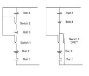
Hard to know what is best without knowing what you are trying to acheive, but heres a couple of suggestions you can look at. Maybe some fuses might be a good idea too! HTH

batts_change.JPG
 
That pic makes no sense to me lol. I was thinking of having it 36v but power boost to 48v handy from just a switch
or 24v in place of 36v or all 3 i dunno.

your pics are too tech for me. This is advanced as my wiring diagrams go . lol..
1265460895.jpg
 
02jze said:
That pic makes no sense to me lol. I was thinking of having it 36v but power boost to 48v handy from just a switch
or 24v in place of 36v or all 3 i dunno.

your pics are too tech for me. This is advanced as my wiring diagrams go . lol..
1265460895.jpg

Why not just use the full 48V all the time?
 
02jze said:
Just to have different power for different days. like when i ride to the pub have 48v but when i ride home use 24v hahaha
Fair enough. I'm thinking that maybe you don't have any throttle or controller. The batteries are connected through a switch straight to the motor. Is that correct?
 
That's going to have more to do with what space you have to put them in than anything else--you'll need to figure out what shape and size you have to work with, then figure out how the batteries will best layout within that space, before you can figure out how to connect them. :)
 
amberwolf said:
That's going to have more to do with what space you have to put them in than anything else--you'll need to figure out what shape and size you have to work with, then figure out how the batteries will best layout within that space, before you can figure out how to connect them. :)

Yes..sorry..I should have included that. :(

I am planning on fitting 100 A123 into an augmented space within the frame of my MTB, the triangular piece where the cross bar, diagonal and upright meet. I dont know whether to go for a "perfect fit" triangle or whether to make up 8 cell packs with balance tabs and charge them with a Turnigy Accucell. Even if I knew that, I still would not be sure of how to connect the packs to come out with the 72v 11 Ah which 100 A123 M1 cells should provide.

I will probably need pictures to better inform people, so I will take care of that tomorrow.
Cheers. :p
 
The Mighty Volt said:
I am planning on fitting 100 A123 into an augmented space within the frame of my MTB, the triangular piece where the cross bar, diagonal and upright meet.
Assuming you mean the front triangle's toptube, downtube, and seattube (the "bike shop" names for the three main tubes of the front triangle), the first thing to determine is if indeed 100 of them *can* fit there.

Each one is 28mm diameter, give or take a bit. Assuming staggered rows for least space wastage, and that they'll be in a "single file" pattern so there is only one "layer" of them, with the ends of the cells pointed left and right of the bike, perpendicular to the bike's length. Then there is the thickness of whatever you use to space them apart a bit so they can't rub on each other and short out. Then the thickness of whatever you use to encase them so they don't rub on the bike frame itself.

FWIW, the overall idea is a common one for triangle-mounted packs of cylindrical cells. It is one possible plan I am considering for my LiPo/LiCo cells, once I get a BMS for them to safely use them without risk of destruction. ;)

I dont know whether to go for a "perfect fit" triangle or whether to make up 8 cell packs with balance tabs and charge them with a Turnigy Accucell. Even if I knew that, I still would not be sure of how to connect the packs to come out with the 72v 11 Ah which 100 A123 M1 cells should provide.

Assuming they all fit, then for 3.3V per cell to get 72V you have to put 22 cells in series (72.6V, actually, nominal, though they could be as high as 3.6V+ per cell bringing the pack hot-off-the-charger voltage to at least 79.2V).

Assuming 2.3Ah per cell, then for 11Ah you'd need 5 strings of 22 cells in parallel, which actually comes out to 11.5Ah.

That's a total of 110 cells you'll actually need to fit in that triangle, plus insulation/casing/etc.

As for how to build it pack-wise, it depends on how you intend to charge it. If you are going to use an 8s charger, you're only going to be able to charge a bit more than two thirds of the pack that way, as it will be two 8s sections and one 6s section. So you also need a 6s charger, unless the 8s is a smart charger that can deal with 6s as well.

What I sort of planned to do with my LiPo/LiCo cells was build them into ~12V sections, as if they were SLAs. So they'll actually be about 14.8V sections, wired up in 4S blocks. Conveniently, the Fechter/Goodrum v2.6 BMS was in 4S sections, so each little board could go with a "mini pack", with interconnects to all the others in series, *or* to a separate control board (which I'd have to cut off of it's own little 4S board, since it's not normally separate). That way I don't have a whole bunch of little balancing cables running off to a main BMS board--I just have the series interconnect wires, which should be fewer in number.

I could then use these "12V blocks" to build whatever pack I needed for that testing or operating configuration, since it seems most common to use 12V increments for controller voltages. If I wanted I could parallel several sets series'd together, and then just series *all* of the sets together to charge them, without worrying about disconnecting/connecting the balance wires.


The actual wiring of your pack could be 5 separate series strings of 22 cells, or it could be 22 stacked parallel-wired sets of 5. I think the latter approach is the more recommended one from what I have read around the web, but it has it's disadvantages, too (if one cell dies totally shorted it'll take out everything directly paralled with it--not a likely scenario but a possible one).


I will probably need pictures to better inform people, so I will take care of that tomorrow.
[/quote]
You'll also need to get dimensions of the inside of the triangle, so that you can verify they'll fit.

One way to do this is to take a photo of the side view of the triangle from as far away as you can get with your camera and still use it's optical zoom function to fill the screen as fully as possible with the triangle. That way you can use that as a reference in the computer to begin drawing circles in it to determine if it will all fit.

Alternately, just lay the bike frame on it's side (this is easiest if it has no cranks or handlebars or seat on it, but usually just taking off the pedal from one side and taking the front wheel out will let it lay flat enough to do this). Then start placing actual cells in there, sitting on their ends on the floor, to see if they will indeed all fit in that space and leave you room for casing around them and such.
 
Hi amberwolf. Thanks for that informative post!

I already conducted a very basic experiment to the effect that I took a sheet of ply, held it to one side of the triangle, and went around the far side with my pencil and drew the outline from the interior of the triangle.

Then I measured each battery and figured out how much I needed to extend the frame by.

Finally, I began to arrange the batteries on the pencil outline and found that, from what I can gather, I can definitely fit 100 on the triangle, absolutely.

Of course, once glue, insulation, wires etc begin to play their part....it may drop a bit

72v is the predominating feature, as the controller is 72v controller.

The Capacity only becomes pertinent when you consider {a} the basic necessity of range itself and {b} the more technical necessity of providing the requisite 50A to the controller.

I think 10Ah should secure both of those requirements...albeit in a limited fashion.

Stand by for pics...and thanks for your time. :!:
 
This is probably really simple, really bad, and has been uploaded before....but
Heres my schematics to run the Kelly KDS48200 at 48V with SLA's

edit: its based off of the schematics that kelly provided, but with a circuit breaker instead of a contactor....its essentially a simplified version of theirs, with no reverse circuit for a fixed magnet motor
 

Attachments

  • SCHEMATICS COLOR.PNG
    282.5 KB · Views: 6,966
Back
Top