the +12 is just to drive the relay and can be created with a 3 terminal regulator like the 7812, or a current limiting resistor could be used to drop the voltage. the 7812 will only work with input voltage <35v or so, but i have used them up to 40v. the low current required to drive the relay should make it ok, or you could just put diodes like a in4001 in series with the input of the 7812 to drop the voltage a volt each.
the simplest thing to do is to use a series resistor between the charger and the + end of the relay, making sure the resistor can dissipate the required power. you can calculate the resistor using ohm's law. i'm sorry, but if you cannot do that this may be beyond your present skill level.
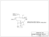
the circuit i suggested assumes that you set the pots at the end of charge or discharge, which may have been a bit misleading. i apologize for assuming you should know that, which is an invalid assumption on my part. in order for the voltage divider setpoints to remain stable, they must be divided down from a regulated or known voltage.
the low voltage cutoff will work based on using the cutoff voltage for the value at the top of the resistive divider at the end of discharge, because above that voltage there will be enough to keep q1 on. . the high voltage cutoff will work the same; at voltages below the endpoint there will not be enough voltage to divide down to trigger q2.
if your supply voltage is constant, the current to the battery will decrease as the state of charge increases. most battery chargers use loosely regulated supplies, or they use a constant current, which increase in voltage with the state of charge.
if you adjust the pots during actual use the voltage dividers would be based on the voltage of the charger at that state of charge or discharge,so it should work. as i said, this circuit is just a rough starting point, and a regulated voltage to the top of the voltage dividers would make it much more accurate.
when i have a bit more time i will analyze the function of the circuit more thoroughly and i may have some refinements, but if you adjust the pots to trigger the respective transistors at the end of charge/discharge i think it will work ok. nobody would likely build a commercial product with this simple circuit, but it is a place to start.
when calculating the trigger points, the voltage of the charger at those points must be known. thus, for the end of charge, we assume that say 36v is the proper level. the actual voltage will be divided down and if the pot is adjusted to trigger the end of charge when the voltage is 36v it will work properly. you will have to watch the system with a meter and set the pots to end charge/discharge when the voltage is close to the endpoint.
don't feel like you are less than somebody else because you don't know this; i'm sure you know things i don't. there is some pleasure in the application of my knowledge to help somebody else achieve their desired task, otherwise all that time i spent studying is not worth much in the grand scheme.

")